
A special-shaped gradual exhaust structure with low flow pressure loss

A low-flow, special-shaped technology, applied to engine components, machines/engines, and leakage prevention, to achieve the effects of reducing flow mixing losses, improving efficiency and reducing excessive structure

Active Publication Date: 2022-03-15
中国船舶重工集团公司第七0五研究所
View PDF4 Cites 0 Cited by
  • Summary
  • Abstract
  • Description
  • Claims
  • Application Information

AI Technical Summary

Problems solved by technology

[0006] At present, there is no public literature that proposes relevant schemes for the exhaust structure design of single-stage pure impulse steam turbines in a limited space.

Method used


Image

  • A special-shaped gradual exhaust structure with low flow pressure loss
  • A special-shaped gradual exhaust structure with low flow pressure loss
  • A special-shaped gradual exhaust structure with low flow pressure loss

Examples


Embodiment Construction

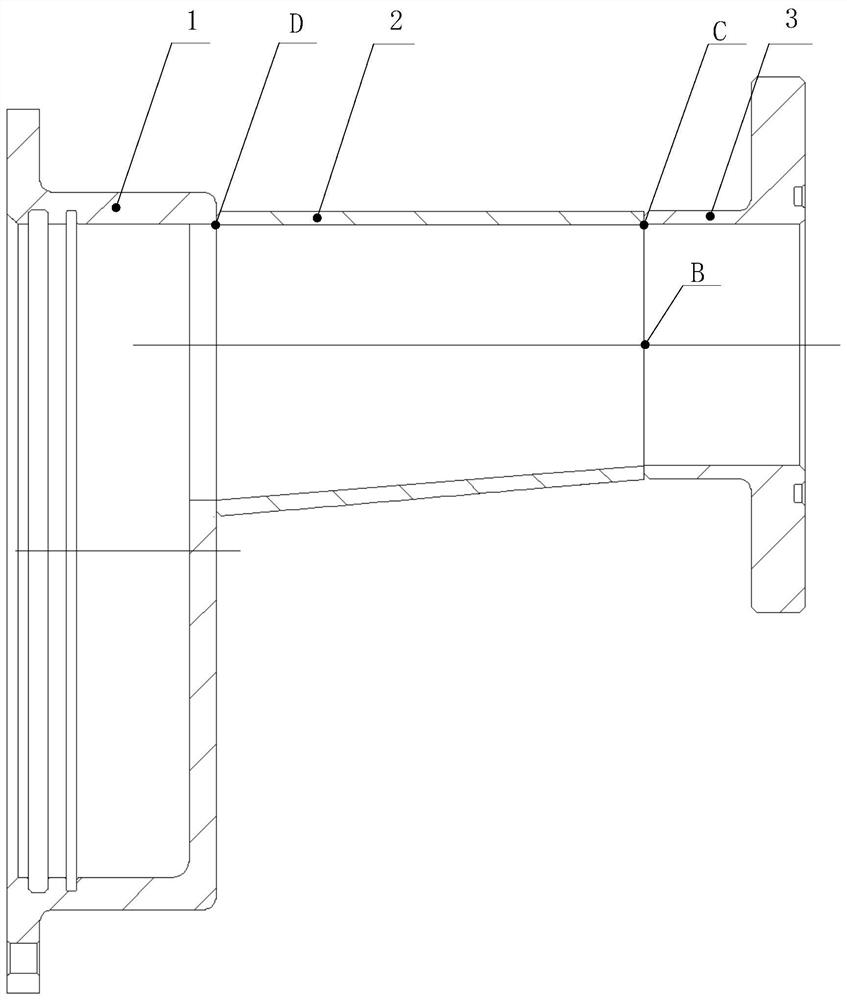
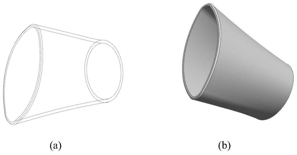
[0029] The low-flow pressure loss special-shaped gradual exhaust structure proposed by the present invention is composed of a gas collection shell, a special-shaped gradual change exhaust pipe, and an exhaust shell flange, such as figure 1 As shown, the gas collection shell, the special-shaped gradual exhaust pipe, and the flange of the exhaust shell are sealed and connected by welding. The gas collection shell is connected to the casing of the nozzle box of the steam turbine through 6 bolts. High-temperature asbestos pad seal, the exhaust shell flange is connected with the condenser gas distribution flange through six bolts and sealed with a copper pad.

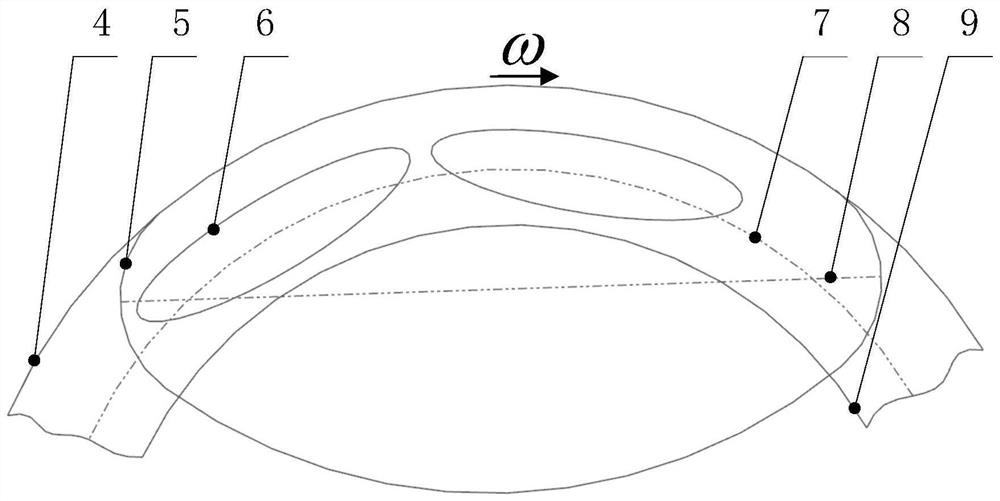
[0030] The working principle of the present invention is: after the high-temperature and high-pressure steam expands and accelerates through the zoom nozzle of the steam turbine, it flows out at a high Mach number and ultra-high speed, and a part of the steam maintains a high-speed state and directly impacts the special-shape...


PUM


Abstract

The invention proposes a special-shaped gradual exhaust structure with low flow pressure loss, which is composed of a gas collection shell, a special-shaped gradual exhaust pipe, and an exhaust shell flange; the exhaust pipe-like elliptical inlet is designed according to the flow characteristics in the steam turbine to avoid gap leakage The flow loss caused by the direct impact of exhaust steam and other steam after working on the wall of the gas-collecting shell, and the gradual change of the flow channel is designed to reduce the loss of the mixing process, and realize the low-flow exhaust effect of the small working medium flow steam turbine. This structure Through the design of the flow channel, the exhaust pressure loss is reduced, the back pressure of the steam turbine is reduced, the internal flow is improved, and the exhaust section is made compact, which can be used for closed cycle steam turbine power in special environments such as underwater and space.

Description

technical field [0001] The invention relates to the technical field of steam turbine exhaust structure for closed cycle power with small working fluid flow, in particular to a special-shaped gradual exhaust structure with low flow pressure loss. Background technique [0002] Closed cycle power steam turbines with small working fluid flow in underwater, space and other special environments are very different from ordinary steam turbines. They are characterized by high wheel speed, large nozzle expansion ratio, single-stage pure impulse It has the characteristics of low gas rate, large relative blade tip clearance, and high exhaust steam velocity at the outlet of moving blades. [0003] The steam turbine power system is extremely sensitive to the back pressure of the steam turbine; if the back pressure is too high, the flow condition in the steam turbine channel will become poor, the flow loss will increase, the heat power conversion capacity will decrease, the waste heat at t...

Claims


Application Information

Patent Timeline
Patent Type & Authority Patents(China)
IPC IPC(8): F01D25/30F01D25/24F01D11/00
CPCF01D25/30F01D25/24F01D25/243F01D11/003F01D11/005
Inventor 郭兆元白超王贤义李程黄立
Owner 中国船舶重工集团公司第七0五研究所
Learn More