Combined detection method of ultrasonic longitudinal wave reflection method and diffraction time difference method, and TOFD probe applied therein

A time-of-diffraction time-of-flight and joint detection technology, which is applied to the analysis of solids using sound waves/ultrasonic waves/infrasonic waves, the use of sound waves/ultrasonic waves/infrasonic waves for material analysis, and measuring devices, etc., can solve problems such as undetectable defects and difficulties in horizontal position positioning , to achieve the effect of perfect ultrasonic automatic and semi-automatic detection and good detection ability

Inactive Publication Date: 2020-01-14
HARBIN ELECTRIC CORP QINHUANGDAO HEAVY EQUIP
View PDF6 Cites 2 Cited by
  • Summary
  • Abstract
  • Description
  • Claims
  • Application Information

AI Technical Summary

Problems solved by technology

[0004] 1. Defects near the surface of the detection surface cannot be detected;
[0005] 2. Defects near the bottom surface of the detection surface cannot be detected;
[0006] 3. The disadvantag...

Method used


Image

  • Combined detection method of ultrasonic longitudinal wave reflection method and diffraction time difference method, and TOFD probe applied therein
  • Combined detection method of ultrasonic longitudinal wave reflection method and diffraction time difference method, and TOFD probe applied therein
  • Combined detection method of ultrasonic longitudinal wave reflection method and diffraction time difference method, and TOFD probe applied therein

Examples


Embodiment 1

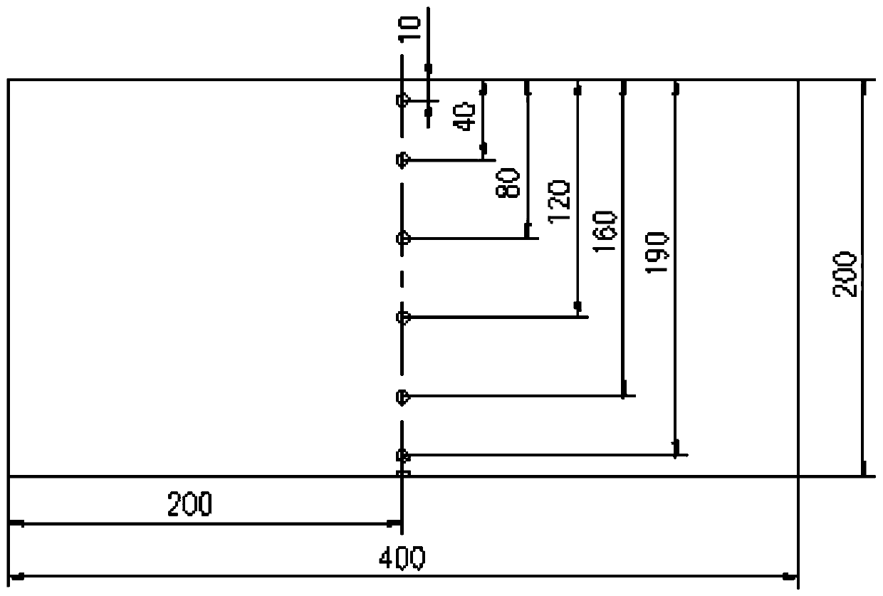
[0173] Verify detection method of the present invention on calibration test block M, wherein, calibration test block M is a rectangle, and its thickness is 200mm, and length is 400mm, and width is 200mm. At the center of the upper surface of the calibration test block M, there are 6 horizontal holes evenly distributed along the thickness direction, and the centers of the 6 horizontal holes are located on the same straight line. The horizontal hole is a cylinder with a diameter of 2mm and a length of 60mm. The axis of the horizontal hole is parallel to the width direction of the calibration test block M, and the distances from the upper surface of the calibration test block M are 10, 40, 80, 120, 160 and 190mm in sequence. There is a rectangular slot directly below the sixth horizontal hole, the slot depth is 2mm, the slot width is 2mm, and the slot length is 60mm.

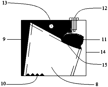
[0174] The probe 7 is a curved TOFD probe, which forms a pair of TOFD probes with the probe 7 on the other side...

Embodiment 2

[0179]For the butt weld with a thickness of 200mm, the method of the present invention is used for detection. The probe and calibration test block adopted in embodiment 2 are the same as in embodiment 1, and the specific operations are as follows: the probe 6 is placed on the calibration test block M described in embodiment 1 , Probe 6 is 15mm away from the center line of the horizontal hole, obtain the reflected echo of the horizontal hole with a depth of 10mm, adjust its wave height to 80% of the full screen height, and use this sensitivity as the reference sensitivity of probe 6. Set the material sound velocity (5920m / s) on the instrument, use the horizontal hole with a depth of 10mm to calibrate the probe delay, and the calibration of probe 6 is completed. Then place the probe 6 on one side of the weld to be tested, 15mm away from the groove of the weld to be tested.

[0180] Place the probe 7 on both sides of the weld to be inspected, and the center distance is calculated...

experiment example 1

[0195] Experimental Example 1 Probe Diffusion Angle Test

[0196] According to the requirements of NB / T47013.10-2015, the 12dB sound beam spread angle test was carried out. The spread angle test results of the conventional TOFD probe and the TOFD probe in Example 1 are shown in Table 1.

[0197] Table 1 Probe diffusion angle test results

[0198]

[0199] It can be seen from the test results that, under the similar refraction angle, wafer size and frequency, the divergence angle of the curved wafer TOFD probe is much larger than that of the traditional TOFD probe.


PUM


Abstract

The invention discloses a combined detection method of an ultrasonic longitudinal wave reflection method and a diffraction time difference method. The combined detection method comprises the followingsteps that 1, a TOFD probe and a creeping wave probe are installed on a scanning frame; 2, TOFD probe parameters and creeping wave probe parameters are set; 3, a workpiece is scanned; and 4, an imageis analyzed after the scanning is finished. According to the method, the defects that defects near a near surface and a bottom surface are missed and a plurality of pairs of probes need to be adoptedfor thick welding seams in an existing TOFD detection method are overcome, and ultrasonic automatic and semi-automatic detection is more perfect.

Description

technical field [0001] The invention relates to an automatic detection method for three ultrasonic probes, in particular to an automatic detection method for ultrasonic waves combining diffraction and reflection. Background technique [0002] Time of Flight Diffraction (TOFD for short) is an ultrasonic testing method that uses the diffracted wave signal of the defect to detect and measure the size of the defect. It usually uses a longitudinal wave oblique probe and adopts a send-and-receive mode. After the transmitting probe emits the ultrasonic pulse wave, first it is the through wave reaching the receiving probe, and then the bottom reflection wave. Between the through wave and the bottom reflection wave, if there is a defect, the diffraction wave of the defect will be received. [0003] TOFD technology is one of the cutting-edge technologies in the field of ultrasonic testing. Using this technology to detect weld defects has the characteristics of fast detection speed, hi...

Claims


Application Information

Patent Timeline
IPC IPC(8): G01N29/06G01N29/24
CPCG01N29/069G01N29/2437G01N2291/0289G01N2291/044G01N2291/267
Inventor 张建磊邓显余程仲贺夏珊余金涛魏荣帅刘朋顺邓屾张杰
Owner HARBIN ELECTRIC CORP QINHUANGDAO HEAVY EQUIP
Why Eureka
Try Eureka