Welding structure for avoiding Mini LED displacement

A technology of welding structure and displacement, applied in the direction of printed circuits, optics, instruments, etc. connected with non-printed electrical components, can solve problems such as color shift

Inactive Publication Date: 2020-01-14
INTERFACE TECH CHENGDU CO LTD +2
View PDF5 Cites 0 Cited by
  • Summary
  • Abstract
  • Description
  • Claims
  • Application Information

AI Technical Summary

Problems solved by technology

[0004] However, as shown in Figures 2A and 2B, during soldering, since the solder 15 will be heated and appear in a liquid state, the two pins 121 and 122 of the Mini LED 12 are likely to be formed due to the fluid flow of the liquid solder 15. One-sided offset of 16, away from the position of the two welding points, after the solder 15 is cooled and solidified into a solid, the two pins 121, 122 of the Mini LED12 form a single-sided offset of 16 welding, resulting in one-sided solder 15 over There is too much solder 15 on the other side (as shown in Figure 2C), too much solder 15 on one side will cause the light source of the Mini LED12 to project on the excessive solder 15, and reflect different chromaticity, so that The different chromaticities are mixed to the luminous color of the Mini LED12, resulting in color shift
[0005] It can be seen that there are still many deficiencies in the above-mentioned commonly used items, which are not really good designers and need to be improved urgently.

Method used


Image

  • Welding structure for avoiding Mini LED displacement
  • Welding structure for avoiding Mini LED displacement
  • Welding structure for avoiding Mini LED displacement

Examples


Embodiment Construction

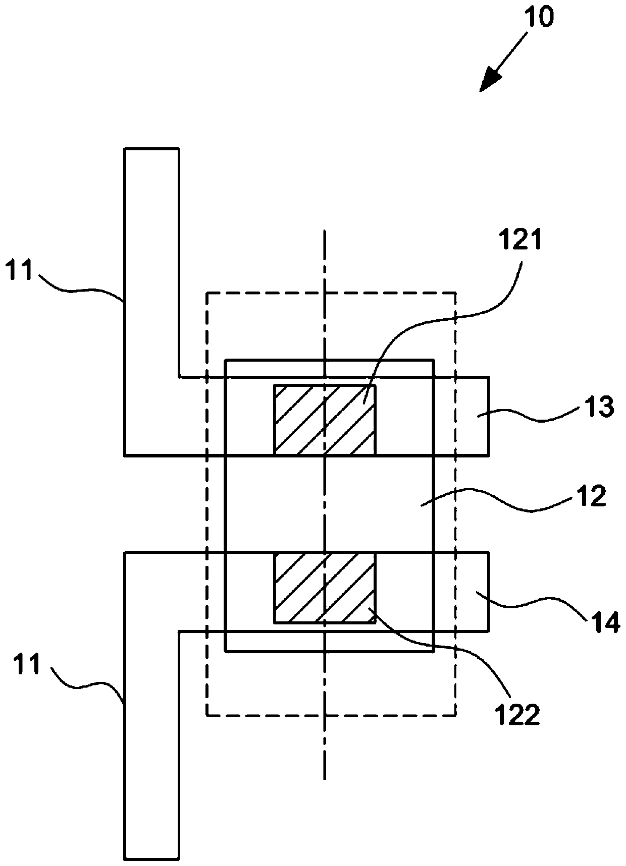
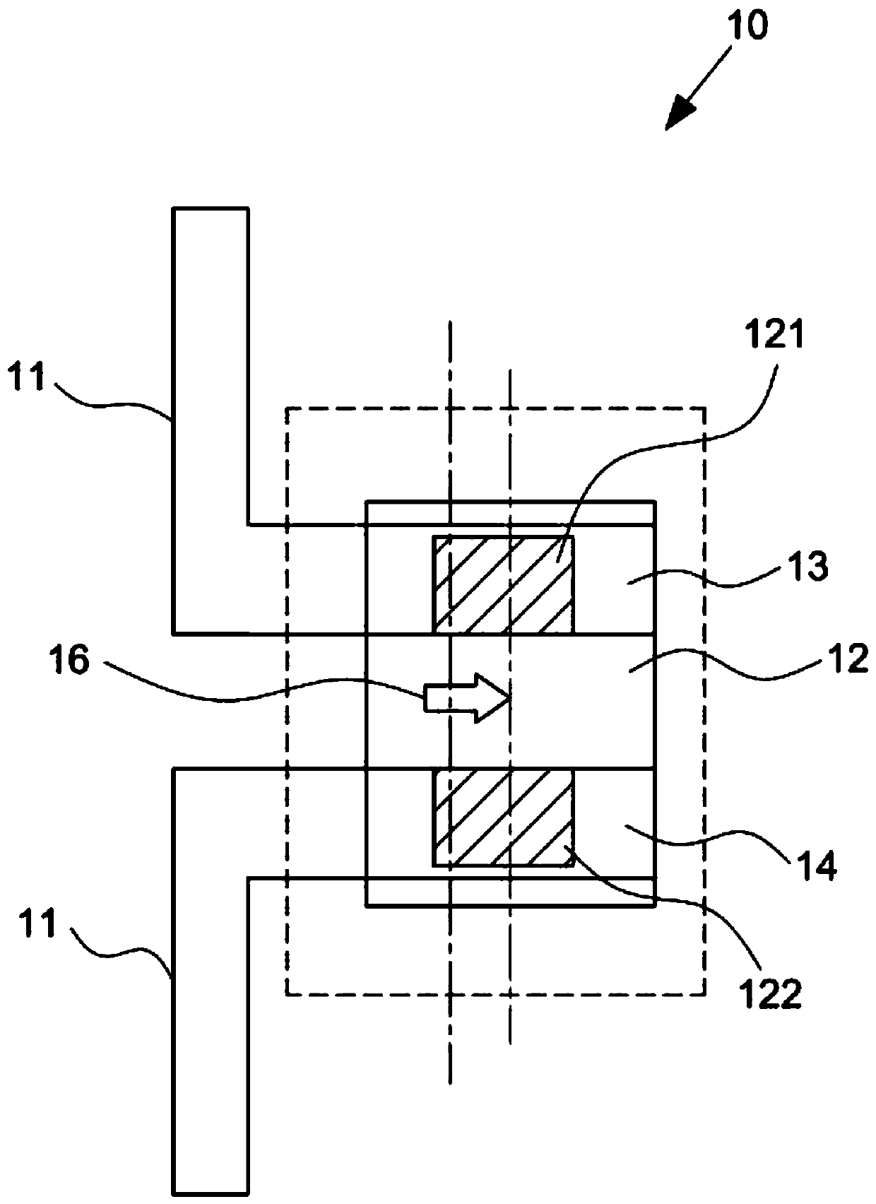
[0022] This invention is about a "welding structure to avoid Mini LED displacement", please refer to image 3 , Figure 4 , Figure 5 As shown, the welding structure for avoiding displacement of the Mini LED in the present invention mainly includes: a pair of metal sheets 30 .

[0023] Wherein, the pair of metal sheets 30 are arranged on the circuit 31 of a circuit board 3 for connecting a Mini LED40, and the pair of metal sheets 30 are located at the two pins 41 and 42 corresponding to the Mini LED40, respectively on the upper and lower sides. Two notches 32 are symmetrically provided to form two welding points for welding the Mini LED 40 .

[0024] With the composition of the above components, when the two pins 41, 42 of the Mini LED40 are soldered to the two soldering points, the two notches 32 of the pair of metal sheets 30 can be positioned and stop the flow of liquid solder, so as to The mutual traction force generated by the surface tension effect of the liquid solde...


PUM


Abstract

The invention discloses a welding structure for avoiding Mini LED displacement. The welding structure comprises a pair of metal sheets, wherein the pair of metal sheets is arranged on a circuit of a circuit board and used for being connected with a Mini LED, and two notches are symmetrically formed in the positions, corresponding to two pins of the Mini LED, of the upper side and the lower side ofthe pair of metal sheets respectively to form two welding points for welding the Mini LED, therefore, when the two pin punching pieces of the Mini LED are welded at the two welding points, the two gaps of the pair of metal sheets can be positioned and can stop flowing of fluid of the liquid soldering tin, so that, the two pins of the Mini LED can be correctly welded on the two welding points, single-side deviation is avoided, excessive soldering tin on one side and little soldering tin on the other side are exposed, and after welding, a light source of the Mini LED is prevented from being projected onto the soldering tin cooled and solidified into a solid, and the color cast caused by color mixing of different chromaticity is avoided.

Description

technical field [0001] The present invention is a welding structure for avoiding displacement of Mini LED, especially a structure for avoiding displacement of welding points when Mini LED is welded on a circuit board. Background technique [0002] The trend of display development has entered into the development that requires high contrast ratio and wide color gamut, so that the display can show more natural colors and present more lively and vivid images. The next-generation display technology will replace the backlight module in the existing LCD with Mini LED, which can show the characteristics of power saving, thinness and light-emitting efficiency. [0003] Press, the commonly used Mini LED welding structure, please refer to Figure 1, it is on the line 11 of a circuit board 10, and a pair of metal sheets 13 and 14 parallel to each other are provided at the position where a Mini LED 12 is connected. The center lines of the two metal sheets 13, 14 respectively have a weld...

Claims


Application Information

Patent Timeline
IPC IPC(8): H05K1/18G02F1/13357
CPCG02F1/133603G02F1/133612H05K1/18
Inventor 林荣松黄达人张建文
Owner INTERFACE TECH CHENGDU CO LTD
Why Eureka
Try Eureka