Denitration device for reducing ammonia escape and coal-fired boiler system

A ammonia escape and denitrification technology, applied in the field of coal-fired boilers, can solve problems such as abnormality, safety, economic impact, unsafe boiler equipment load limit, etc., and achieve the effect of preventing ammonia escape and making it easy to pick and place

Inactive Publication Date: 2020-01-17
DATANG HUANGDAO POWER GENERATION
View PDF0 Cites 1 Cited by
  • Summary
  • Abstract
  • Description
  • Claims
  • Application Information

AI Technical Summary

Problems solved by technology

The blockage of the air preheater caused unsafe incidents of boiler equipment and abnormal load limit of the unit, which brought safety and economic impact to the enterprise
[0004] The inventors found that currently most power plants are only in the state of high-pressure water flushing for air preheater blockage treatment, and have not considered the effects of catalyst compartment gap, nozzle blockage of ammonia gas injection device, and catalyst activity on ammonia escape. , cannot solve the clogging problem of the air preheater quickly and in a targeted manner

Method used


Image

  • Denitration device for reducing ammonia escape and coal-fired boiler system

Examples


Embodiment 1

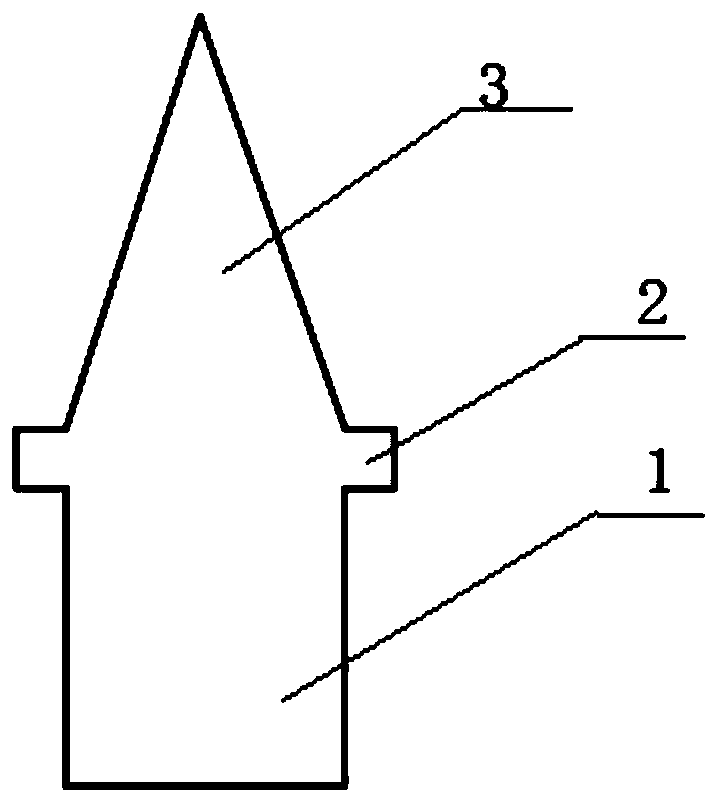
[0034] Such as figure 1 Shown, a kind of denitrification device that reduces ammonia escape of the present embodiment, it comprises:

[0035] A reactor, which is connected with the flue gas channel and the ammonia gas injection device; the reactor is provided with several layers of catalyst compartments, each catalyst compartment is provided with a catalyst, and any two adjacent catalyst compartments are provided with There is a gap between the catalyst compartments, and an ammonia escape structure is installed on the gap between the catalyst compartments; the anti-ammonia escape structure includes a sealing part 1, and the sealing part is used to insert into the gap between the catalyst compartments to seal the gap between the catalyst compartments. The maximum width of the sealing part is equal to the width of the gap between the catalyst compartments, and the length of the sealing part is equal to the length of the gap between the catalyst compartments; both sides of the up...

Embodiment approach

[0039] As an implementation, the ammonia escape prevention structure is a hollow structure.

[0040] Among them, the hollow structure can reduce the weight of the ammonia escape prevention structure and save the manufacturing cost of the ammonia escape prevention structure.

[0041] In this embodiment, the anti-ammonia escape structure is installed on the gap between the catalyst compartments, and the sealing part of the anti-ammonia escape structure is inserted into the gap between the catalyst compartments to seal the gap between the catalyst compartments. At the same time, the protrusion is used to support the sealing part to facilitate the removal of the anti-ammonia escape structure. The guide part at the upper end of the sealing part will also guide the flue gas sent from the flue gas channel into the catalyst compartment, so that the ammonia in the flue gas can react with sulfur trioxide through the action of the catalyst in the compartment to prevent ammonia gas escape...

Embodiment 2

[0052] A kind of coal-fired boiler system of the present embodiment, it is as figure 1 The denitrification unit shown to reduce ammonia slip.


PUM


Abstract

The invention provides a denitration device for reducing ammonia escape and a coal-fired boiler system. The denitration device for reducing ammonia escape comprises a reactor which is connected with aflue gas channel and an ammonia gas injection device, wherein a plurality of layers of catalyst bin grids are arranged in the reactor; a catalyst is arranged in each catalyst bin grid, a catalyst bingrid gap is formed between any two adjacent catalyst bin grids, and an ammonia escape prevention structure is arranged on each catalyst bin grid gap; each ammonia escape prevention structure comprises a sealing part, the sealing part is configured to be inserted into one catalyst bin gap to seal the catalyst bin grid gap, the maximum width of the sealing part is equal to the width of the catalystbin grid gap, and the length of the sealing part is equal to the length of the catalyst bin grid gap; protrusions are arranged on the two sides of the upper end of each sealing part and used for supporting the sealing part; and a flow guiding part is further arranged at the upper end of each sealing part and is used for guiding flue gas conveyed from the flue gas channel into the catalyst bin grid.

Description

technical field [0001] The disclosure belongs to the technical field of coal-fired boilers equipped with denitrification devices, and in particular relates to a denitrification device and a coal-fired boiler system for reducing ammonia escape. Background technique [0002] The statements in this section merely provide background information related to the present disclosure and do not necessarily constitute prior art. [0003] Coal prices continue to rise, causing large areas of power generation companies to suffer losses. After the marketization of electricity coal prices, coal prices have risen far more than electricity prices. The price of electricity and coal has seriously troubled the production and operation of the company. In order to get out of the loss-making predicament, purchasing low-quality economical coal is an inevitable means of turning losses into profits. Therefore, blending medium and high-sulfur coal is the choice of many enterprises. Blending medium- a...

Claims


Application Information

Patent Timeline
IPC IPC(8): B01D53/86B01D53/56B01D53/58
CPCB01D53/8631B01D53/8634B01D2258/0283
Inventor 陈清亮祁成陆源戚鹏张建忠韩晓宁周延飞吴元三张立振蔡成功赵鹏
Owner DATANG HUANGDAO POWER GENERATION
Why Eureka
Try Eureka