
Fin, stirring shaft and tubular reactor

A tubular reactor and stirring shaft technology, applied in the field of stirring shafts, tubular reactors and fins, can solve the problems of poor heat exchange effect of the reactor, affecting normal reaction production, weak mixing effect of the stirring shaft, etc. Product purity, inhibition of crystal sticking to the wall, good removal effect

Inactive Publication Date: 2020-01-17
HIMILE MECHANICAL MFG
View PDF0 Cites 9 Cited by
  • Summary
  • Abstract
  • Description
  • Claims
  • Application Information

AI Technical Summary

Problems solved by technology

[0002] Some existing chemical reactions are carried out in the reactor, which needs to go through filling, reaction, and discharge. During the process, crystallization and sticking to the wall occur, which requires manual cleaning or solvent soaking, which is time-consuming and laborious; at the same time, the mixing effect of the ax-type reaction stirring shaft is weak. The heat exchange effect of the reactor is poor, and the purity of the reaction product is also insufficient; most of the existing tubular reactors also have the problem of crystallization and sticking to the wall of the cylinder, which affects the normal reaction production

Method used


Image

  • Fin, stirring shaft and tubular reactor
  • Fin, stirring shaft and tubular reactor
  • Fin, stirring shaft and tubular reactor

Examples


Embodiment Construction

[0046] This part will describe the specific embodiment of the present invention in detail, and the preferred embodiment of the present invention is shown in the accompanying drawings. Each technical feature and overall technical solution of the invention, but it should not be understood as a limitation on the protection scope of the present invention.

[0047] The embodiments of the present invention will be further described below in conjunction with the accompanying drawings.

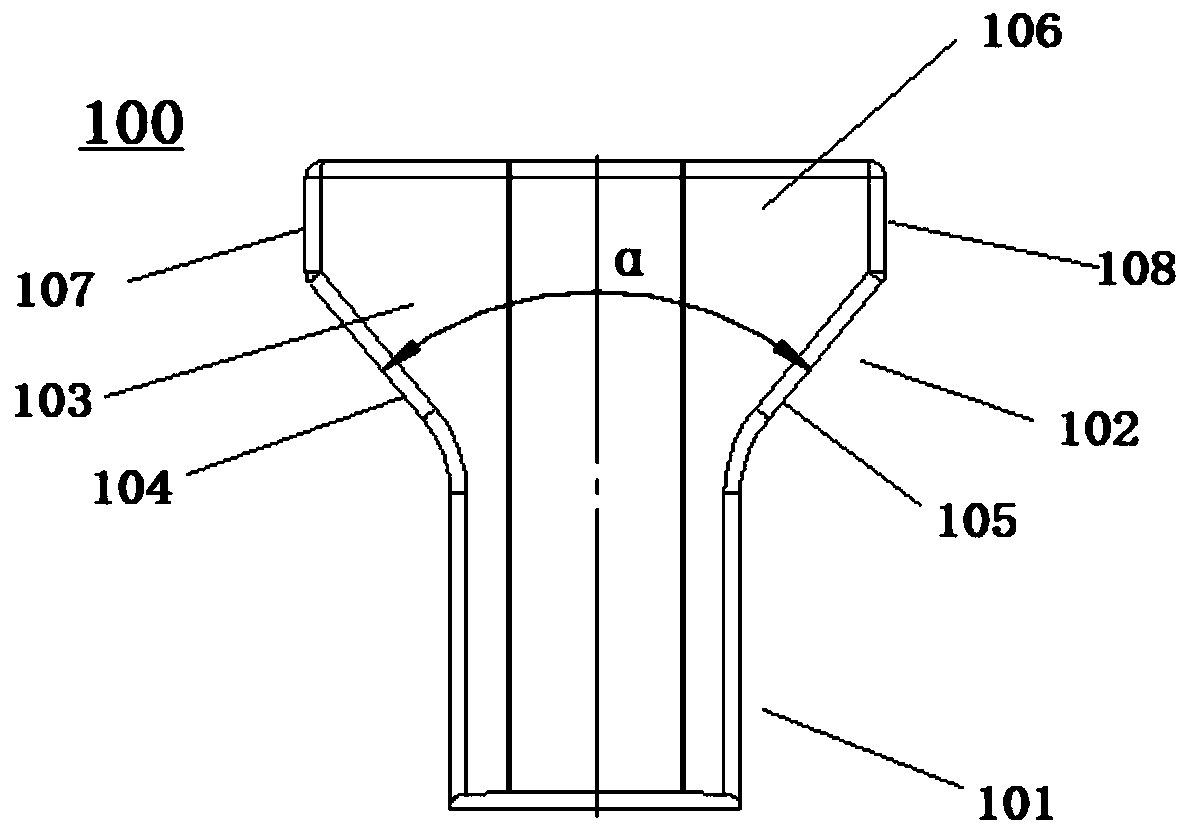
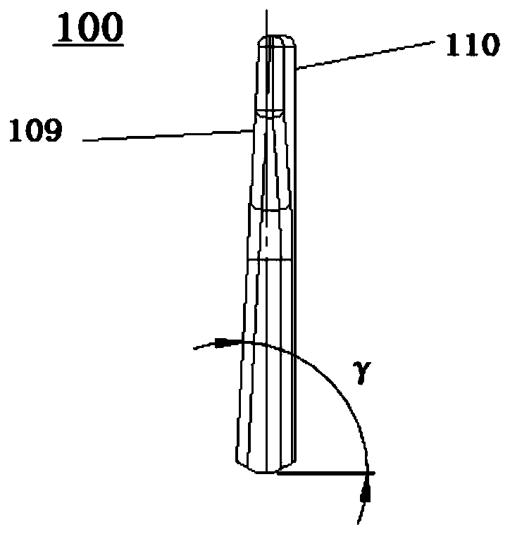
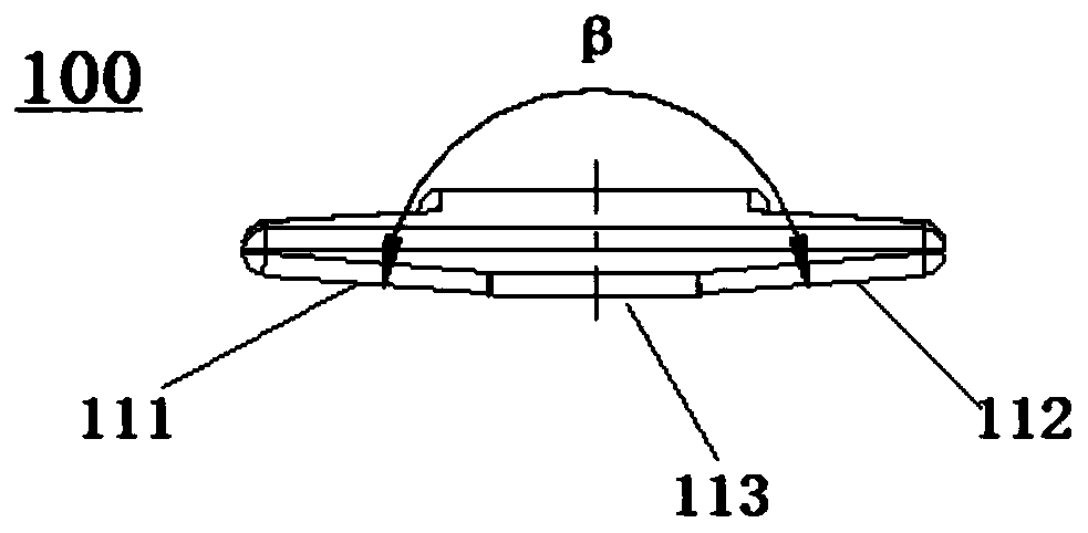
[0048] Such as Figure 1-3 As shown, a fin 100 includes a T-shaped fin body with a liquid-facing surface 110 and a liquid-back surface 109, the T-shaped fin body includes a root 101 and an end 102, and the end 102 includes The expansion part 103 expands to both sides from the junction of the end part 102 and the root part 101 . In this embodiment, the fins are designed as a T-shaped structure, and the T-shaped liquid-facing surface receives a shear area from far to the center due to expansion, which...


PUM


Abstract

The invention relates to a fin, which comprises a T-like fin body with a liquid facing surface and a liquid backing surface, wherein the T-like fin body comprises a root part and an end part, and theend part comprises an expanding part expanding from the connecting position of the end part and the root part to the two sides. According to the invention, the fin can fully refine materials during stirring, and enhance mixing effect; and the invention further provides a stirring shaft with the fin, and a tubular reactor with the stirring shaft.

Description

technical field [0001] The invention relates to the field of chemical equipment, in particular to a fin, a stirring shaft and a tubular reactor. Background technique [0002] Some existing chemical reactions are carried out in a reactor, which needs to go through filling, reaction, and discharge. During the process, crystallization and sticking to the wall occur, which requires manual cleaning or solvent immersion, which is time-consuming and laborious; at the same time, the mixing effect of the ax reaction stirring shaft is weak. The heat exchange effect of the reactor is poor, and the purity of the reaction product is also insufficient; most of the existing tubular reactors also have the problem of crystallization and sticking to the wall of the cylinder, which affects the normal reaction production. Contents of the invention [0003] In order to solve one or more of the above technical problems, the present invention provides a fin, a stirring shaft and a tubular reacto...

Claims


Application Information

Patent Timeline
Patent Type & Authority Applications(China)
IPC IPC(8): B01J19/18
CPCB01J19/1812B01J2219/00085B01J2219/00094
Inventor 安兰翔赵平韩永强唐立星
Owner HIMILE MECHANICAL MFG
Learn More