Building garbage treatment equipment

A technology for processing equipment and construction waste, applied in grain processing, removing smoke and dust, separating dispersed particles, etc., it can solve the problems of easy generation of dust, human injury, and inconvenient movement of garbage disposal devices, and achieves harm prevention, reasonable structure, and high efficiency. Easy to move effect

Inactive Publication Date: 2020-01-17
谢洁萍
View PDF10 Cites 5 Cited by
  • Summary
  • Abstract
  • Description
  • Claims
  • Application Information

AI Technical Summary

Problems solved by technology

[0004] Based on the technical problems that the existing garbage disposal device is inconvenient to move, and dust is easily generated in the process of crushing garbage, which will cause harm to the human body, the present invention proposes a construction waste disposal equipment

Method used


Image

  • Building garbage treatment equipment
  • Building garbage treatment equipment
  • Building garbage treatment equipment

Examples


Embodiment 1

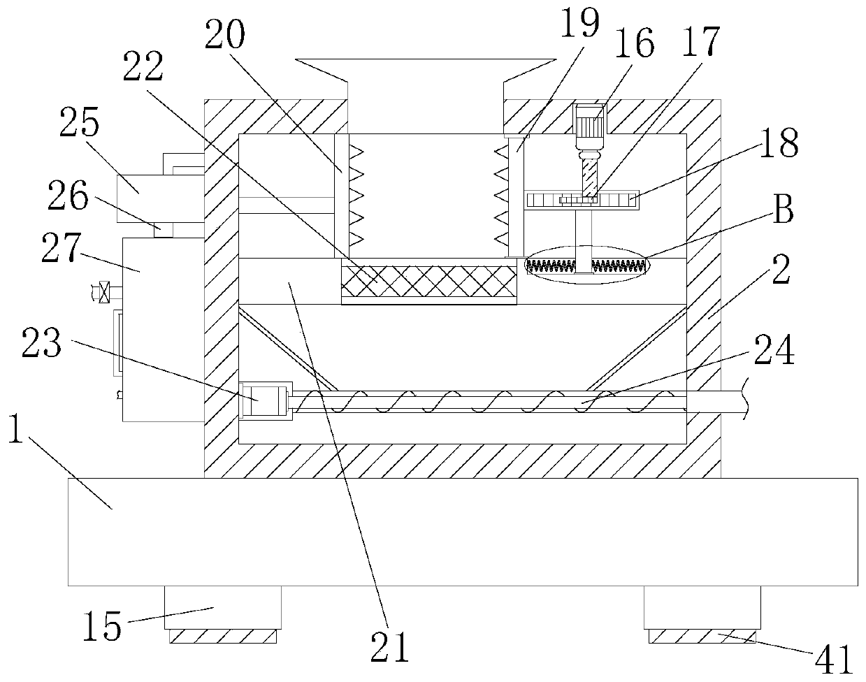
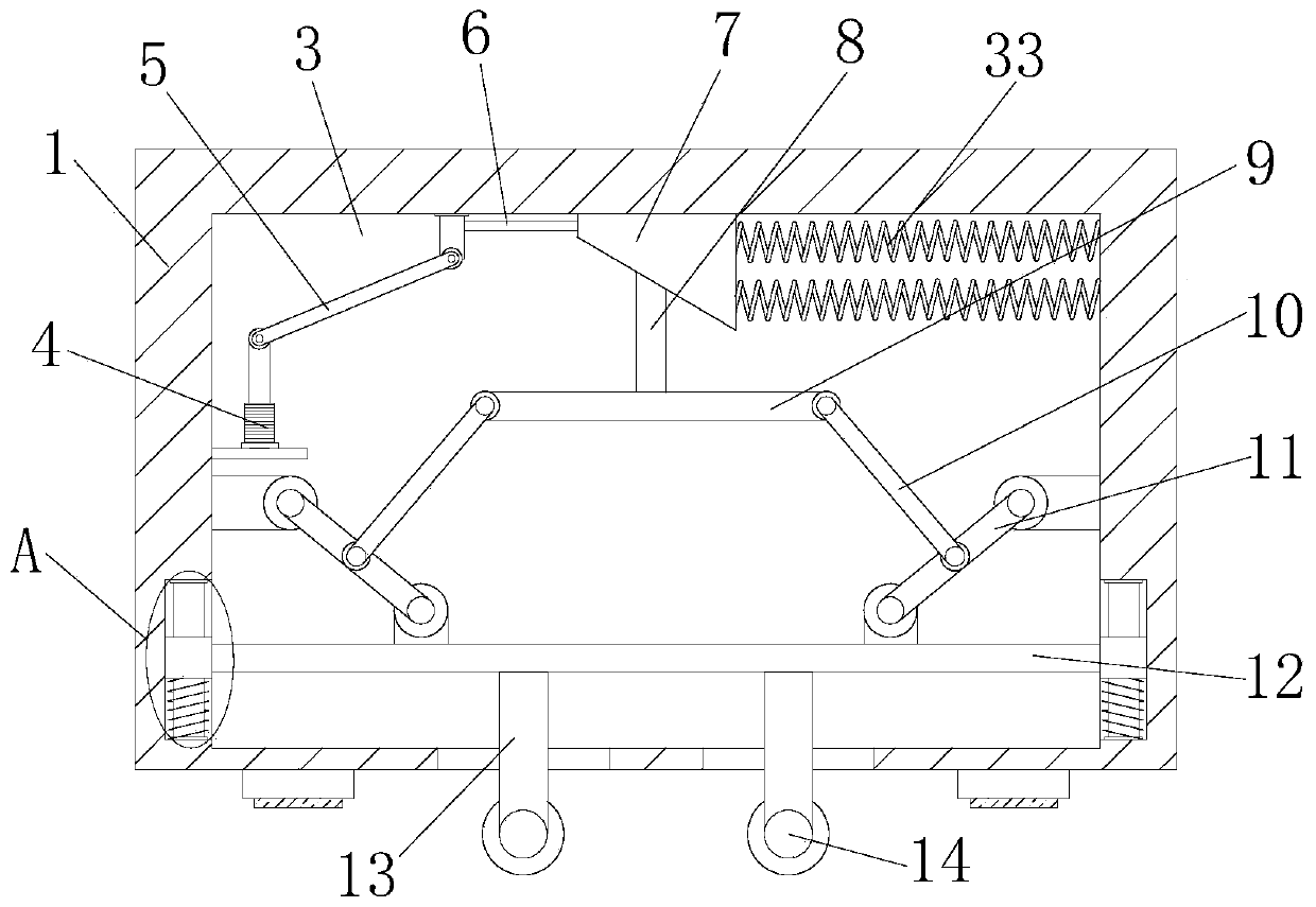
[0026] refer to Figure 1-5In this embodiment, a construction waste treatment device is proposed, including a base 1, a crushing box 2 is fixedly connected to the top of the base 1, a feeding port is provided on the top of the crushing box 2, and an installation chamber 3 is provided on the base 1. An electric push rod 4 is fixedly connected to one side inner wall of the installation chamber 3, and one end of the electric push rod 4 is rotatably connected to a connecting rod 5; Rotately connected with the bottom of the moving plate 6, one side of the moving plate 6 is fixedly connected with a swash plate 7, the top of the swash plate 7 is slidably connected with the top inner wall of the installation chamber 3, and the bottom of the swash plate 7 is slidably connected with a moving rod 8, The bottom end of the moving rod 8 is fixedly connected with a horizontal plate 9, and both sides of the horizontal plate 9 are connected with a first rotating rod 10, and the inner walls of ...

Embodiment 2

[0028] In this embodiment, the crushing assembly includes a first motor 16 fixedly connected to the inner wall of the top of the crushing box 2, a half gear 17 is fixedly set on the output shaft of the first motor 16, and a rectangular plate 21 is fixedly connected in the crushing box 2. The top of the rectangular plate 21 is slidably connected with a rack 18, the rack 18 is intermittently engaged with the half gear 17, and one side of the rack 18 is fixedly connected with a first crushing plate 19, and the top of the first crushing plate 19 is connected to the top of the crushing box 2. The inner wall is slidingly connected, and the inner wall of one side of the crushing box 2 is fixedly connected with the second crushing plate 20, and the side where the first crushing plate 19 and the second crushing plate 20 are close to each other is provided with crushing teeth, and the top of the rectangular plate 21 is provided with Through holes, filter screens 22 are fixedly connected ...


PUM


Abstract

The invention belongs to the field of garbage treatment, in particular to building garbage treatment equipment, and solves the problems of inconvenient movement of a traditional garbage treatment device and injury to human bodies due to dust easily generated in the garbage crushing process. The building garbage treatment equipment comprises a base; a crushing box is fixedly connected to the top ofthe base; a feed port is formed in the top of the crushing box; the base is provided with a mounting cavity; an electric push rod is fixedly connected to the inner wall of one side of the mounting cavity; one end of the electric push rod is rotationally connected with a connecting rod; a moving plate is slidingly connected to the inner wall of the top of the mounting cavity; one end of a connecting rod is rotationally connected with the bottom of the moving plate; and an inclined plate is fixedly connected to one side of the moving plate. The building garbage treatment equipment is reasonablein structure and simple in operation; as the electric push rod enables a moving wheel to make contact with the ground without needing manual conveying of building garbage, the treatment efficiency isimproved; and meanwhile, through effects of a powder sucker and a dust removing box, dust can be treated to prevent injury to human bodies by the dust.

Description

technical field [0001] The invention relates to the technical field of waste treatment, in particular to construction waste treatment equipment. Background technique [0002] Construction waste refers to the dregs, spoils, waste materials, residual mud and other wastes generated during the construction, laying or demolition and repair of various buildings, structures and pipe networks by construction units or individuals. Many wastes in construction waste can be reused as renewable resources after being sorted, removed or crushed. [0003] The existing garbage disposal device is inconvenient to move, and it is easy to generate dust in the process of crushing garbage, which will cause harm to the human body, so we propose a construction waste disposal equipment. Contents of the invention [0004] Based on the technical problems that existing garbage disposal devices are inconvenient to move, and dust is likely to be generated in the process of crushing garbage, which will ...

Claims


Application Information

Patent Timeline
Patent Type & Authority Applications(China)
IPC IPC(8): B02C21/02B02C1/00B02C23/00B08B15/04B01D47/02
CPCB01D47/02B02C1/00B02C21/02B02C23/00B08B15/04
Inventor 谢洁萍
Owner 谢洁萍
Why Eureka
Try Eureka