Dedusting device for crusher

A technology of dust removal device and crusher, which is applied in the direction of dust removal, combination device, cleaning method and utensils, etc., can solve the problems of waste of resources, pollution of the environment, no separation and collection of debris, etc., and achieve easy maintenance and replacement, easy cleaning and recycling, Practical effect

Inactive Publication Date: 2020-01-17
ZAOZHUANG SNKSAN INTELLIGENT MACHINERY CO LTD
View PDF6 Cites 4 Cited by
  • Summary
  • Abstract
  • Description
  • Claims
  • Application Information

AI Technical Summary

Problems solved by technology

[0002] When using a crusher to crush steel waste, it is often accompanied by a large amount of dust, and the direct exhaust will pollute the environment. Nowadays, an exhaust port is generally installed on the crusher, and the dust and debris in the crusher are drawn out by a fan. The dust is collected and cleaned by the cyclone dust collector, but the extracted dust will contain iron debris, and the general dust removal device does not separate and collect the debris, resulting in a waste of resources
[0003] Chinese patent (Notice No. CN 209406554 U) discloses a dust removal device for a steel scrap crusher. The storage box is connected to the dust removal hopper through a fan, and the dust removal hopper is fixed at the air outlet of the crusher, and the dust and debris are collected by the fan. The corrugated hose is introduced into the storage box for dust removal. Dust and debris enter the separation chamber between the top plate and the filter plate, driving the blades and the fixed rod to rotate, and the rotating blades are used to disperse the dust and debris. The magnetic plate absorbs the iron filings on the bottom of the top plate, so as to separate the iron filings from the dust for recycling and ensure the full utilization of resources. Although the device can separate the iron filings, the box is sealed structure, it is not convenient to clean up the iron debris after the work is completed

Method used


Image

  • Dedusting device for crusher
  • Dedusting device for crusher
  • Dedusting device for crusher

Examples


Embodiment 1

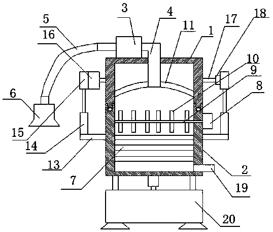
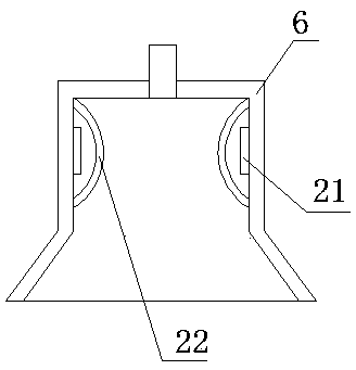
[0024] see Figure 1-4 , in an embodiment of the present invention, a dust removal device for a crusher includes a box body and a base 20, the box body includes an upper box body 1 and a lower box body 2, the upper end of the upper box body 1 is provided with a fan 3, the The fan 3 is provided with a blowing pipe 4 extending into the box, the fan 3 is connected with a dust suction pipe 5, the dust suction pipe 5 is connected with a dust collection cover 6, and the inside of the upper box 1 is provided with a magnet plate 11, The inside of the lower box 2 is provided with a multi-stage dust filter screen 7, and the lower end of the right side of the lower box 2 is provided with an exhaust pipe 19, and the left and right sides of the lower box 2 are provided with a support plate 13, and the support plate 13 The upper side is provided with a first electric telescopic mechanism 14, and the upper end of the first electric telescopic mechanism 14 is provided with a mounting seat 15,...

Embodiment 2

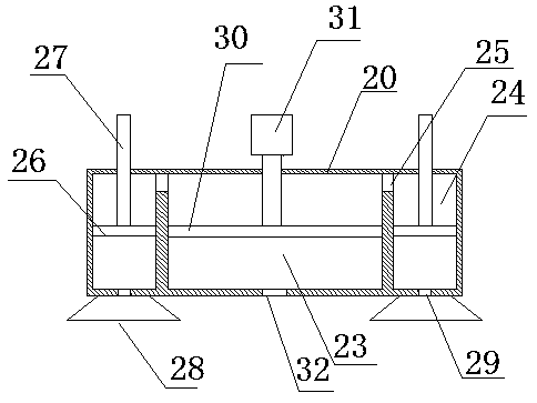
[0029] The inside of the base 20 is provided with a first sliding chamber 23, and the left and right sides of the first sliding chamber 23 are provided with a second sliding chamber 24, and the first sliding chamber 23 and the upper part of the second sliding chamber 24 pass through a first communication channel. The air hole 25 is connected, and the inside of the first sliding chamber 23 is provided with a first piston plate 30, and the upper side of the first piston plate 30 is provided with a second electric telescopic mechanism 31, and the upper end of the second electric telescopic mechanism 31 is installed on At the lower end of the box body, the lower end of the first slide chamber 23 is provided with a second vent hole 32, the inside of the second slide chamber 24 is provided with a second piston plate 26, and the upper side of the second piston plate 26 is provided with a slide rod 27, The upper end of the sliding rod 27 is connected to the lower end of the box body, t...


PUM


Abstract

The invention relates to the technical field of dedusting, in particular to a dedusting device for a crusher. The device comprises a box and a base, the box comprises an upper box body and a lower boxbody, and the left and right sides of the lower box body are provided with supporting plates; the upper sides of the supporting plates are provided with first electric retractable mechanisms, the upper ends of the first electric retractable mechanisms are provided with mounting bases, and a rotation motor is installed on the mounting base of the right side and connected with the upper box body; the right side of the upper box body is provided with a rotation shaft, and the right end of the rotation shaft is connected with the mounting base through a bearing pedestal. Through structural arrangement of the device, after dedusting work is completed, through the first electric retractable mechanisms, the upper box body and the lower box body can be separated, the rotation motor drives the upper box body to rotate so as to adjust the angle of the upper box, iron scraps are conveniently removed and recycled, the time and labor are saved, convenience is also provided for following maintenance and replacement, and the practicability is high.

Description

technical field [0001] The invention relates to the technical field of dust removal, in particular to a dust removal device for a crusher. Background technique [0002] When using a crusher to crush steel waste, it is often accompanied by a large amount of dust, and the direct exhaust will pollute the environment. Nowadays, an exhaust port is generally installed on the crusher, and the dust and debris in the crusher are drawn out by a fan. The dust is collected and cleaned by the cyclone dust collector, but the extracted dust will contain iron debris, and the general dust removal device does not separate and collect the debris, resulting in a waste of resources. [0003] Chinese patent (Notice No. CN 209406554 U) discloses a dust removal device for a steel scrap crusher. The storage box is connected to the dust removal hopper through a fan, the dust removal hopper is fixed at the air outlet of the crusher, and the dust and debris are collected by the fan. The corrugated hos...

Claims


Application Information

Patent Timeline
Patent Type & Authority Applications(China)
IPC IPC(8): B02C23/18B08B15/00B01D50/00
CPCB01D50/00B02C23/18B08B15/007
Inventor 马驰秦娜孙启祥孙法虎
Owner ZAOZHUANG SNKSAN INTELLIGENT MACHINERY CO LTD
Why Eureka
Try Eureka