Hanging type inertia rotary sieve machine

A suspension type and suspension mechanism technology, applied in the direction of filter screen, solid separation, grille, etc., can solve the problems of limited screening, high maintenance cost, large centrifugal force, etc. The effect of different needs

Pending Publication Date: 2020-01-17
腾翎机械科技(云南)有限公司
View PDF0 Cites 0 Cited by
  • Summary
  • Abstract
  • Description
  • Claims
  • Application Information

AI Technical Summary

Problems solved by technology

[0002] The transmission mechanism of the traditional circular sieve machine is the crankshaft type, which is composed of four driven crankshafts on both sides of the sieve bed and the active crankshaft in the middle of the sieve bed. The motor drives the active crankshaft to rotate through multi-stage deceleration, so that the mass point trajectory of the sieve bed is Circular plane movement, this structure requires high flatness of the sieve bed, and high processing and installation precision
At the same time, the traditional flat circular screen machine will generate large vibrations on the frame during the working process, which will affect the service life of the crankshaft and bearings, resulting in a large amount of maintenance and high maintenance costs, and also affect normal production.
In addition, when the traditional flat circular sieve machine is working, the centrifugal force generated by the movement of the sieve bed is relatively large, which may easily cause the whole machine to walk or jump. For this reason, special anchor bolts are required for fixing, and a higher standard foundation is required; moreover , the screens on the existing sieve bed, whether it is one layer or multiple layers, are all fixed structures, not only the screening is limited, but also several shaking screen machines with different layers of screens are required to meet the actual production needs
All of the above will not only increase infrastructure investment, equipment investment and costs, increase the burden on enterprises, but also affect normal production

Method used


Image

  • Hanging type inertia rotary sieve machine
  • Hanging type inertia rotary sieve machine
  • Hanging type inertia rotary sieve machine

Examples


Embodiment Construction

[0027] The present invention will be further described below in conjunction with the accompanying drawings.

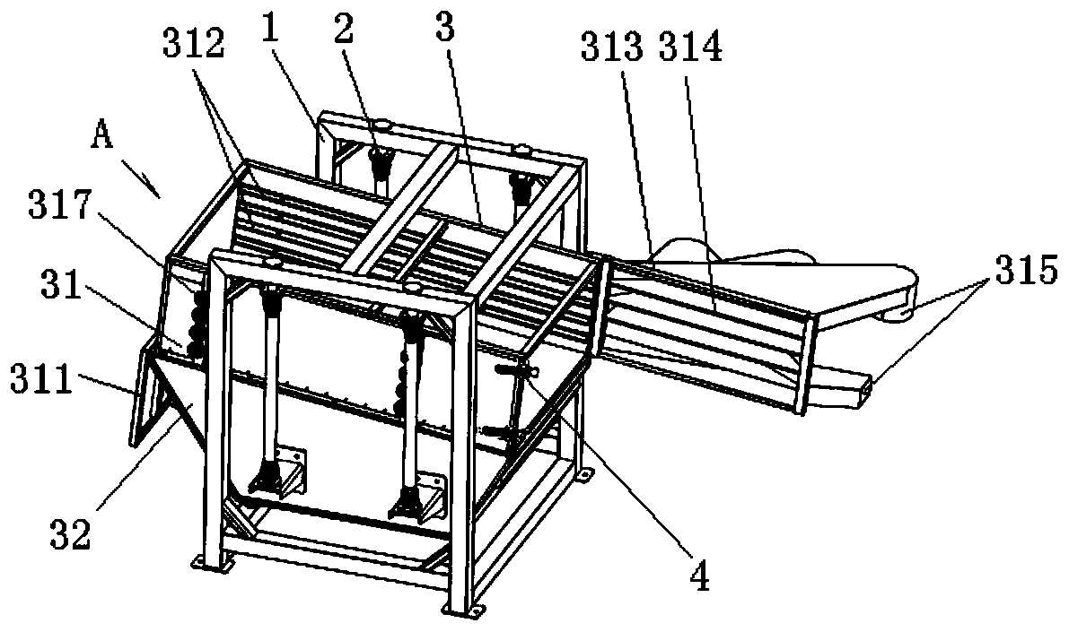
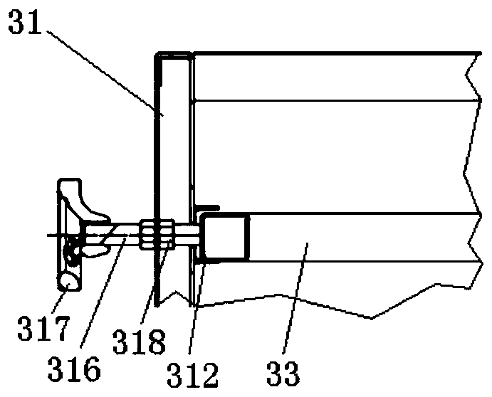
[0028] The suspended type inertial circular sieve machine provided by the present invention comprises a frame 1, and the frame 1 includes a plurality of uprights 11, an upper cross-column 12 and a lower cross-column 13 connected to the upper and lower ends of two uprights 11, suspended by a suspension mechanism 2 The screen body 3 on the frame 1, wherein: the screen body 3 is set as the upper screen frame 31 and the lower screen frame 32, wherein:

[0029] The rear end of the screen frame 31 is hinged with a rear door 311, and the front end is hinged with a discharge part 313. There are a number of slots 312 symmetrically arranged in the screen frame 31, and a screen plate 33 is placed on each symmetrical slot 312, so as to increase or decrease according to needs. The number of layers of the sieve plate 33, the sieve plate 33 is replaced, to meet the screening requirem...


PUM


Abstract

The invention provides a hanging type inertia rotary sieve machine comprising a rack and a sieve body hung on the rack through a hanging mechanism. The hanging type inertia rotary sieve machine is characterized in that the sieve body is arranged to be an upper sieve frame and a lower sieve bracket; a rear door is hinged to the rear end of the sieve frame, and a discharge part is hinged to the front end of the sieve frame; the sieve frame is internally provided with a plurality of bosses or clamping grooves symmetrically; a sieve plate is placed on each symmetrical boss or clamping groove; thesieve bracket comprises front and rear vertical plates; a crossbeam is connected between the front and rear vertical plates; a mounted bearing is arranged in the middle of the crossbeam and is rotationally connected with the middle of a vertical rotary shaft; an eccentric disc or a partial heavy wheel is fixed to the upper end of the vertical rotary shaft; and a partial heavy wheel is fixed to thelower end of the vertical rotary shaft and is connected with a driving wheel on a power machine output shaft through a driving belt. The movement locus of the sieve body is in a plane round shape ora plane oval shape, noise is lowered, the complete machine does not walk or jump any longer, working is high in reliability and stable, the number of layers of the sieve plates can be increased or decreased as needed, the sieve plates are replaced, and sieving needs are met.

Description

technical field [0001] The invention relates to a circular sieve machine, in particular to a suspended inertial circular sieve machine, which belongs to the technical field of mechanical design and manufacture. Background technique [0002] The transmission mechanism of the traditional circular sieve machine is the crankshaft type, which is composed of four driven crankshafts on both sides of the sieve bed and the active crankshaft in the middle of the sieve bed. The motor drives the active crankshaft to rotate through multi-stage deceleration, so that the particle trajectory of the sieve bed is Circular planar movement, this structure requires high flatness of the sieve bed, as well as high processing and installation precision. At the same time, the traditional flat circular screen machine will generate large vibrations on the frame during the working process, which will affect the service life of the crankshaft and bearings, resulting in a large amount of maintenance and ...

Claims


Application Information

Patent Timeline
Patent Type & Authority Applications(China)
IPC IPC(8): B07B1/28B07B1/42B07B1/46
CPCB07B1/286B07B1/42B07B1/46B07B1/4609
Inventor 杨海波
Owner 腾翎机械科技(云南)有限公司
Why Eureka
Try Eureka