Cleaning machine

A cleaning machine and cleaning rack technology, applied in the field of cleaning machines, can solve the problems of inconvenient operation, many impurities in cleaning liquid, and reduced work efficiency, and achieve the effects of simple and convenient operation, ensuring accurate limit, and preventing materials from flying out.

Inactive Publication Date: 2020-01-17
上海峰梅光学科技有限公司
View PDF10 Cites 1 Cited by
  • Summary
  • Abstract
  • Description
  • Claims
  • Application Information

AI Technical Summary

Problems solved by technology

The traditional design has limited materials for each cleaning, and because the material rack is directly placed in the cleaning tank for cleaning, after several cleanings, the cleaning liquid contains more impurities, and the cleaning liquid needs to be replaced frequently, which is very troublesome, which leads to its work Reduced efficiency
In the prior art, impurities are cleaned by setting a filter screen, but this requires regular replacement and cleaning of the filter screen, and its operation is relatively inconvenient, and fully automatic cleaning cannot be realized, and its work efficiency is still low

Method used


Image

  • Cleaning machine
  • Cleaning machine
  • Cleaning machine

Examples


Embodiment Construction

[0028] Embodiments of the present invention will be further described below in conjunction with the accompanying drawings.

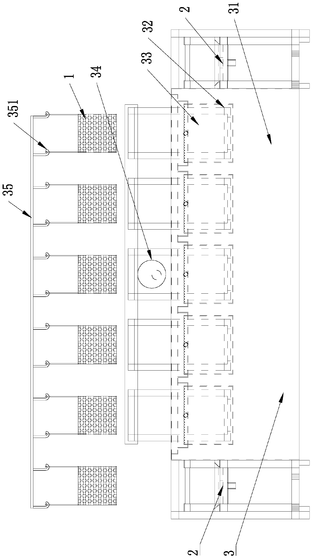
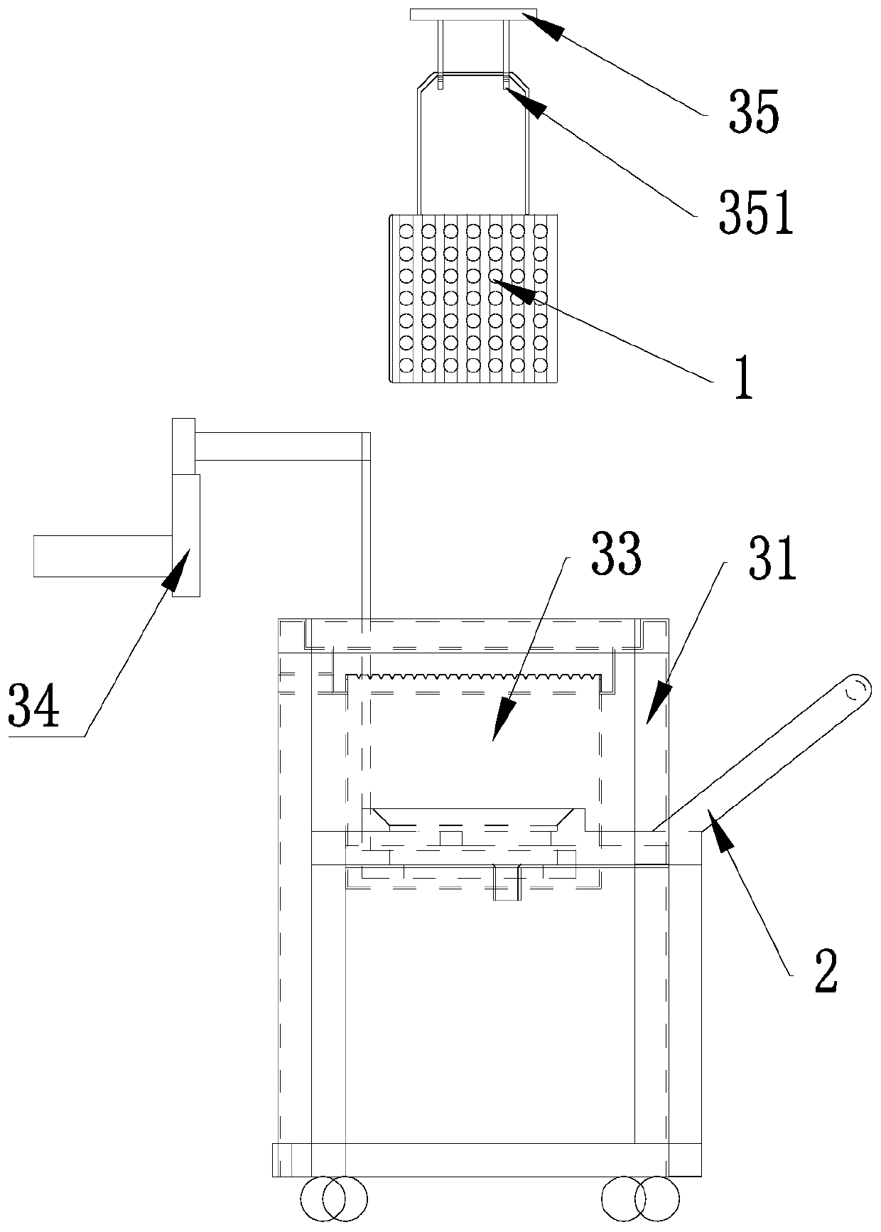
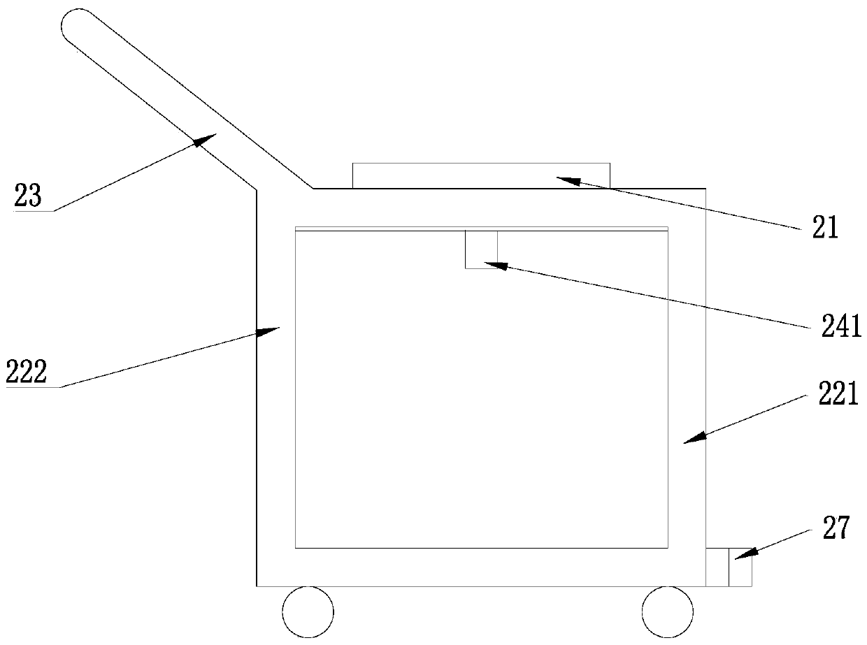
[0029] Such as Figure 1-7 As shown, the present embodiment relates to a washing machine, including a material rack 1, a material transport trolley 2, a cleaning transmission device 3 and a dehydration device 4, and the cleaning transmission device 3 includes a cleaning rack 31, and both ends of the cleaning rack 31 are provided with an accommodating trough, the material transport trolley 2 is placed in the holding tank, the material transport trolley 2 is provided with a limit tray 21 for placing the material rack, the cleaning rack 31 is provided with a plurality of cleaning tanks 32, and each cleaning tank 32 is provided with a The overflow tank 33 , the top edge of the overflow tank 33 is zigzag, and the dehydration device 4 is provided with a plurality of fixing grooves 41 for clamping the material rack 1 .

[0030] Such as Figure 3-5 As shown, i...


PUM


Abstract

The invention discloses a cleaning machine. The cleaning machine comprises a material shelf, a conveying trolley, a cleaning transmission device and a water removal device. The cleaning transmission device comprises a cleaning shelf, the two ends of the cleaning frame are each provided with a containing groove, the conveying trolley is arranged in the containing grooves, the conveying trolley is provided with a limiting tray used for placing the material shelf, multiple cleaning grooves are formed in the cleaning shelf, an overflow groove is formed in each cleaning groove, the top end edge ofeach overflow groove is in a sawtooth shape, and multiple fixed grooves used for clamping of the material shelf are formed in the water removal device. The overflow grooves are formed in the cleaninggrooves, the top end edges of the overflow grooves are designed to be in the sawtooth shape, it is ensured that in the cleaning process, the liquid face height of cleaning liquid can be ensured whilethe cleaning liquid with impurities is discharged, and the overflow grooves are in the clean state all the time.

Description

technical field [0001] The invention relates to the field of washing machines, in particular to a washing machine. Background technique [0002] In the existing cleaning equipment, the material is usually placed in the material rack, and then the material rack is directly placed in the cleaning tank through the transmission device, and then the material is cleaned by rotating the material rack or vibrating the cleaning liquid. After cleaning Take it out and spin dry. The traditional design has limited materials for each cleaning, and because the material rack is directly placed in the cleaning tank for cleaning, after several cleanings, the cleaning liquid contains more impurities, and the cleaning liquid needs to be replaced frequently, which is very troublesome, which leads to its work Reduced efficiency. In the prior art, impurities are cleaned by setting a filter screen, but this requires regular replacement and cleaning of the filter screen, and its operation is relat...

Claims


Application Information

Patent Timeline
Patent Type & Authority Applications(China)
IPC IPC(8): B08B3/14B08B13/00F26B5/08
CPCB08B3/14B08B13/00F26B5/08
Inventor 王敏
Owner 上海峰梅光学科技有限公司
Why Eureka
Try Eureka