Bearing cover angle positioning machining process equipment

A technology of angle positioning and processing technology, which is applied in the direction of positioning devices, metal processing equipment, metal processing machinery parts, etc., and can solve the problem that the tile knife positioning device has no angle auxiliary positioning mechanism, the tile cover cannot be clamped in place, manual adjustment and positioning, etc. problems, to achieve the effect of improving flexibility and convenience, and improving practicability

Inactive Publication Date: 2020-01-17
十堰宏兆汽配实业有限公司
View PDF1 Cites 0 Cited by
  • Summary
  • Abstract
  • Description
  • Claims
  • Application Information

AI Technical Summary

Problems solved by technology

[0006] In order to solve the above technical problems, the present invention provides a tile angle positioning processing technology equipment to solve the problem that the existing tile positioning device has no angle auxiliary positioning mechanism, and the tile cannot be clamped in place at one time according to the required processing angle. It often requires multiple clamping and manual adjustment of positioning, which is extremely low in efficiency and low in precision

Method used


Image

  • Bearing cover angle positioning machining process equipment
  • Bearing cover angle positioning machining process equipment
  • Bearing cover angle positioning machining process equipment

Examples


Embodiment

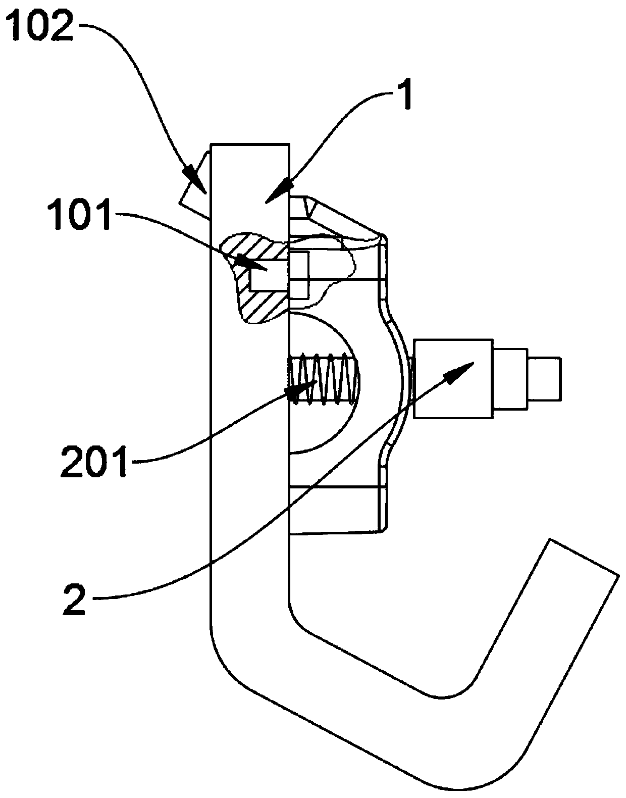
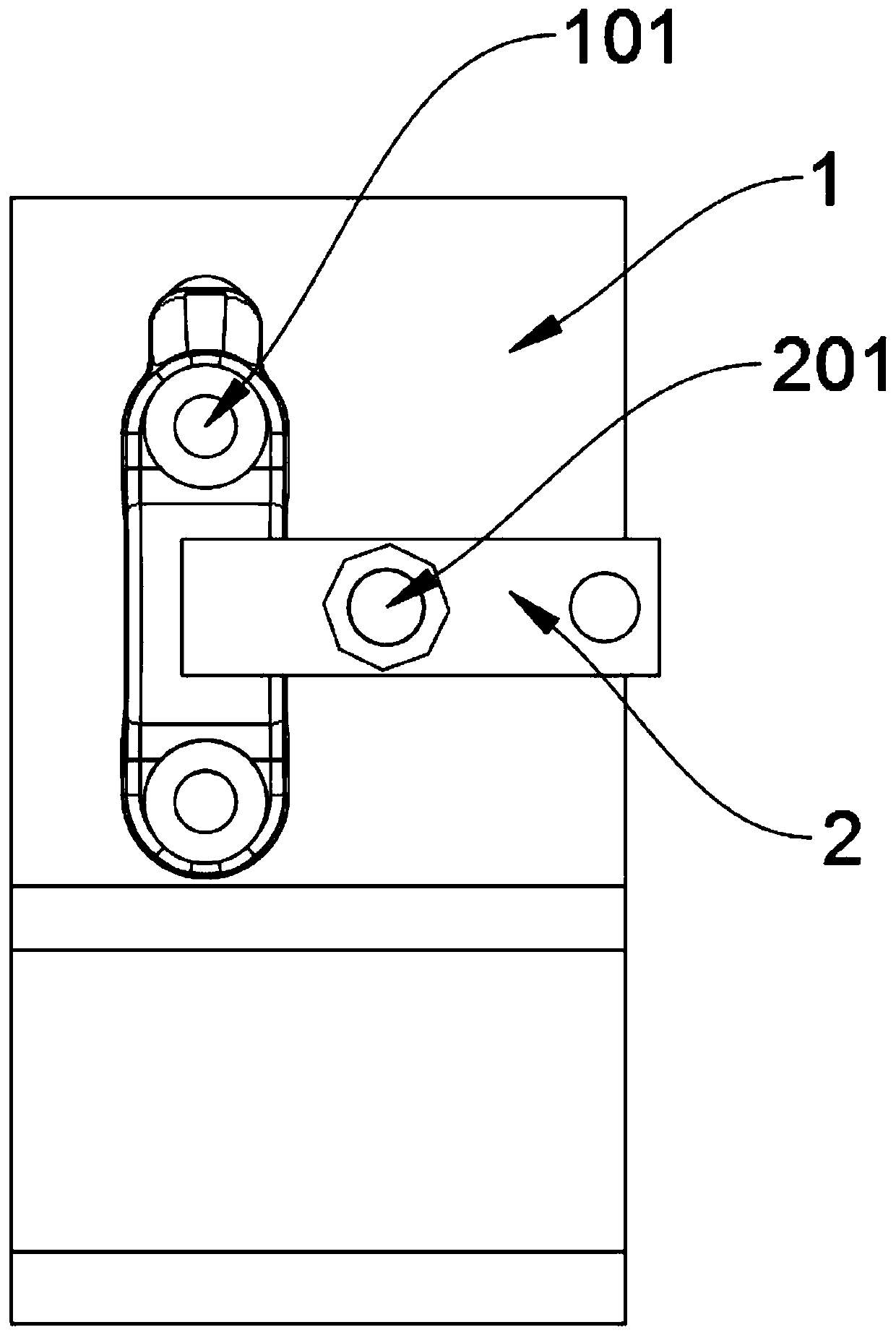
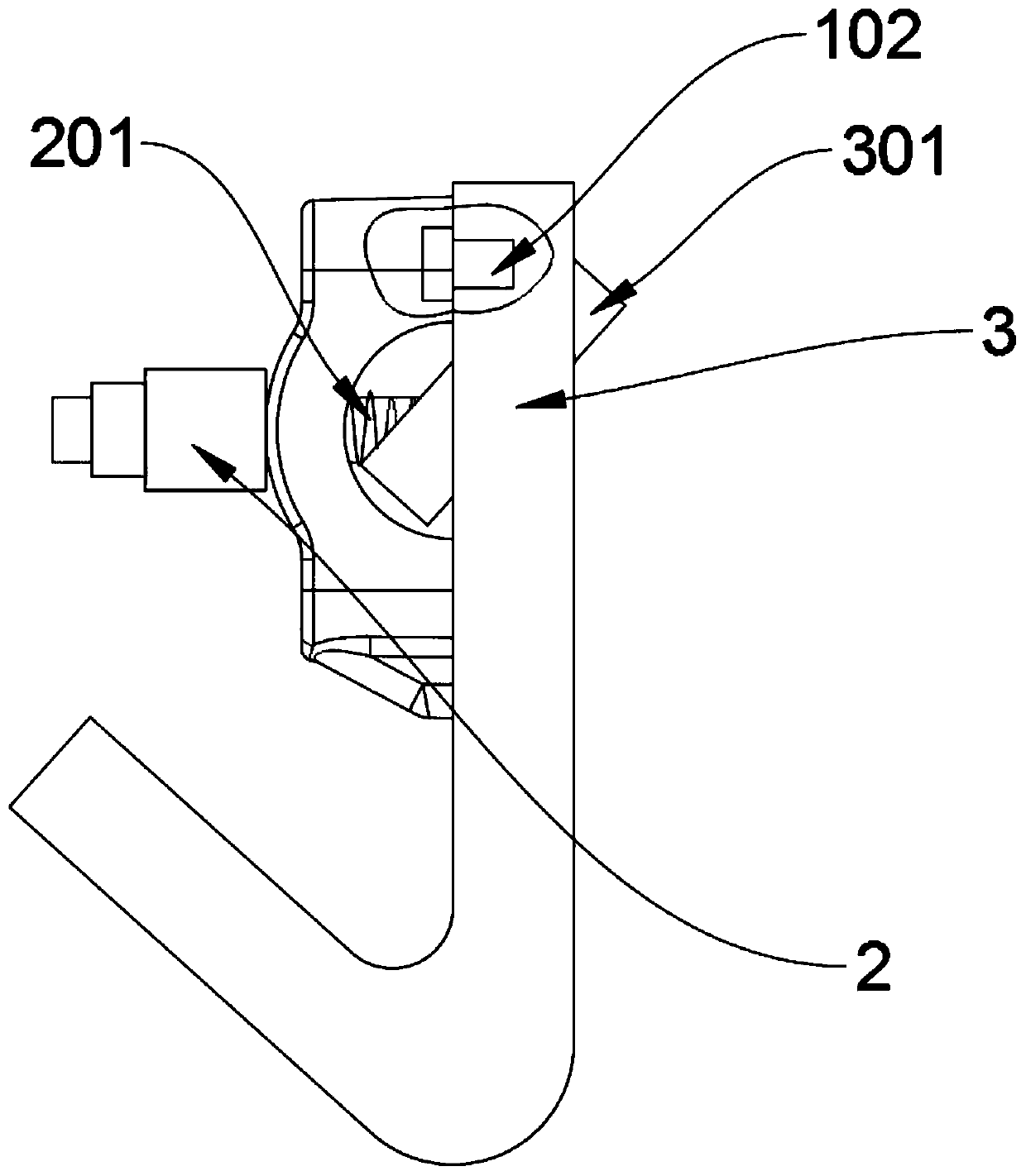
[0029] as attached figure 1 to attach Figure 4 Shown:

[0030] The present invention provides a tile cover angle positioning processing equipment, including a clamp body a1, a pressure plate 2, and a clamp body b3; the top surfaces of the clamp body a1 and clamp body b3 are provided with threaded rods 201; the bottom of the clamp body a1 is designed with double knuckles , the bottom of clamp body b3 is designed with a single corner, as attached figure 1 And attached image 3 As shown, this design enables the staff to select the fixture that needs to be used at a glance during construction, which is convenient and quick, and improves the practicability of the device; the top surfaces of the clamp body a1 and the clamp body b3 are provided with positioning pins 101, And the positioning pin bar 101 is provided with two on the top surface of the clamp body a1 and the clamp body b3, as attached figure 1 , attached figure 2 , attached image 3 And attached Figure 4 As show...


PUM


Abstract

The invention discloses bearing cover angle positioning machining process equipment and relates to the technical field of machining. The bearing cover angle positioning machining process solves the problems that an existing bearing cover positioning device is not provided with an angle auxiliary positioning mechanism, multiple clamping and manual adjustment positioning are often needed, the efficiency is extremely low, and the precision degree is not high. The bearing cover angle positioning machining process equipment comprises a clamp body a, a pressing plate and a clamp body b. A threaded rod is arranged on the top surfaces of the clamp body a and the clamp body b. The pressing plate penetrates the threaded rod and is movably connected to the outer side of the threaded rod. According tothe device, an original tool needing manual adjusting and positioning is optimized for treatment, the positioning is completed once by using the pressing plate and positioning pin rods, the drillingangle can be accurately positioned through an inner drilling sleeve a and an inner drilling sleeve b, the production time is greatly saved, the clamping positioning time is shortened, the qualification rate of products is increased, and stability of the products is improved.

Description

technical field [0001] The invention belongs to the technical field of mechanical processing, and more specifically relates to a tile angle positioning processing technology equipment. Background technique [0002] As the driving system of the car, the engine is the source of all the power of the car and is an extremely important part of the car. The bearing pad of the crankshaft is also called the sliding bearing, which mainly plays the role of supporting load and transmitting motion between the housing holes, and the bearing pad is the main friction pair. The tile cover is a component provided for installing the bearing cover, and it is fixed on the cylinder block of the engine. [0003] For example, the patent application number: CN201821757571.X discloses a tooling fixture for bearing pad covers, which includes: a horizontal bottom plate, the front and rear ends of the bottom plate are fixed on two side plates one by one, and the two The two side plates are fixed on th...

Claims


Application Information

Patent Timeline
Patent Type & Authority Applications(China)
IPC IPC(8): B23B41/00B23Q3/00
CPCB23B41/00B23Q3/00B23Q2703/10
Inventor 李宏张玉斌杨善华刘富生张义奎刘明荣
Owner 十堰宏兆汽配实业有限公司
Why Eureka
Try Eureka