
Auxiliary device for high-accuracy shearing machining

A high-precision, assembly-plate technology, which is applied in the direction of shearing devices, shearing machine accessories, positioning devices, etc., can solve problems such as poor effect of workpiece limit and fixation, adjustment of clamping and fixing parts of the device, and affecting the application effect of specification workpieces. , to achieve the effect of improving the processing quality of the workpiece and ensuring the cutting accuracy

Inactive Publication Date: 2020-01-17
HUBEI HAILIAN TECH CONSULTATION CO LTD
View PDF1 Cites 0 Cited by
  • Summary
  • Abstract
  • Description
  • Claims
  • Application Information

AI Technical Summary

Problems solved by technology

[0003] In order to solve the above-mentioned technical problems, the present invention provides an auxiliary device for high-precision shearing processing to solve the problem that the auxiliary device used in the existing shearing processing operation has a poor effect on the positioning and fixing of the workpiece. Displacement is prone to occur during cutting operations, which affects the cutting accuracy of the workpiece; and the adjustable effect of the device is poor, and the clamping and fixing parts of the device cannot be flexibly adjusted according to the workpiece specifications, which easily affects the application effect of the device to workpieces of different specifications

Method used


Image

  • Auxiliary device for high-accuracy shearing machining
  • Auxiliary device for high-accuracy shearing machining
  • Auxiliary device for high-accuracy shearing machining

Examples


Embodiment

[0024] as attached figure 1 To attach Figure 5 Shown:

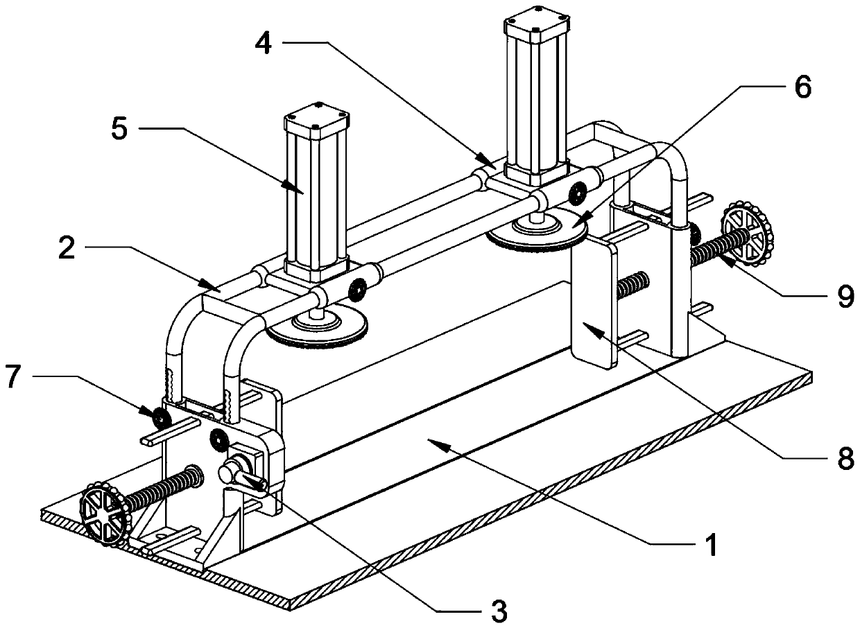
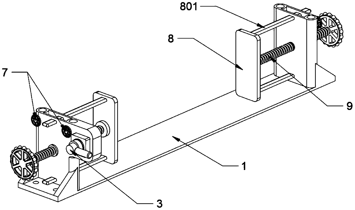
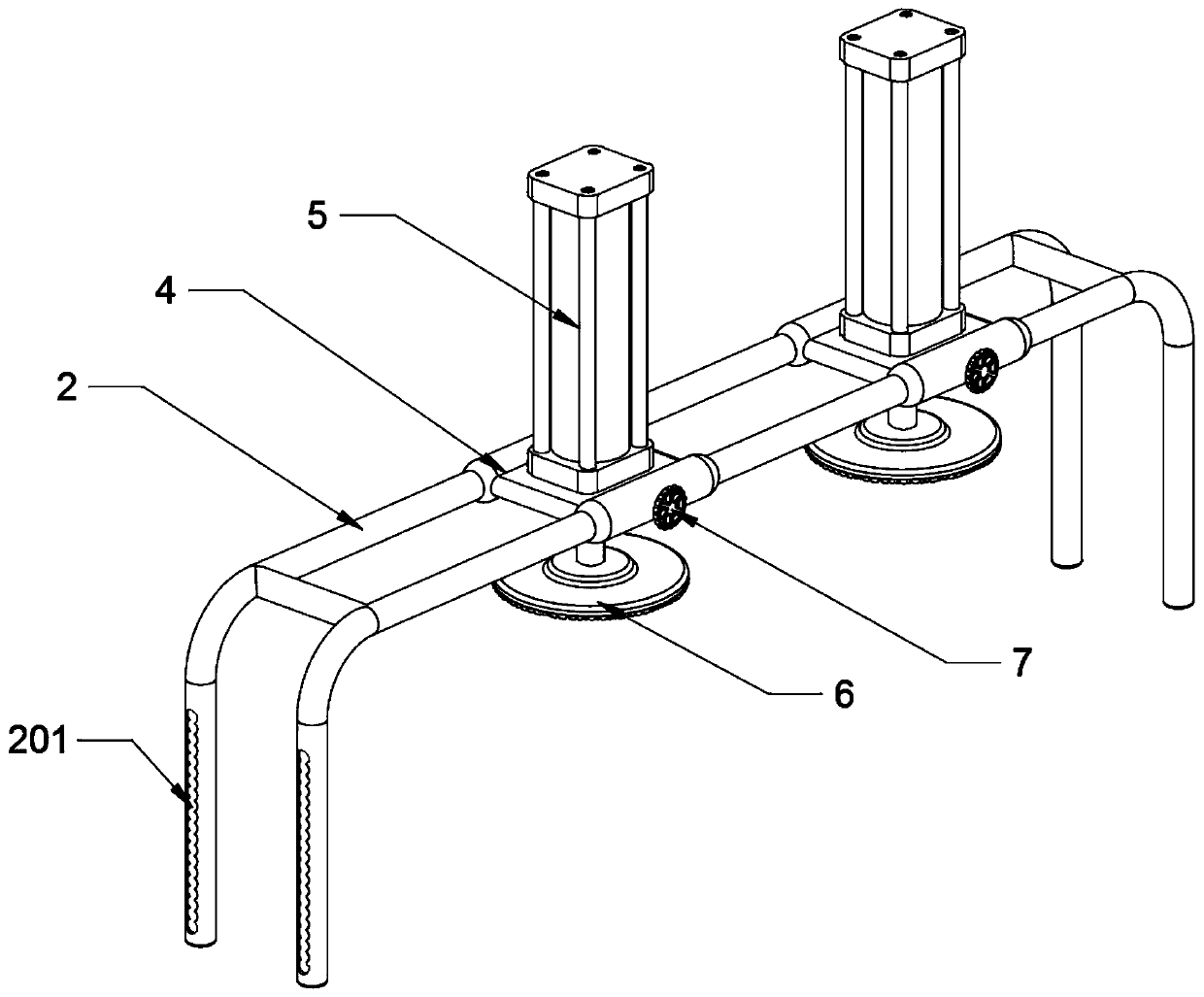
[0025] The invention provides an auxiliary device for high-precision shearing processing, which includes a base 1, a receiving frame 2, a limit groove 201, an air control valve 3, an assembly plate 4, an air cylinder 5, a clamping plate 6, and fixing bolts 7. Limiting plate 8, limiting slide rod 801 and adjusting screw 9; the receiving frame 2 is a frame structure, and the receiving frame 2 is installed on the top of the base 1, and two limiting slots are provided on the left and right sides of the bottom of the receiving frame 2 201; the air control valve 3 is installed on the outer end surface on the right side of the base 1, and the air control valve 3 is connected to the external air supply pipe; the assembly plate 4 is slidably installed on the top of the receiving frame 2, and the cylinder 5 is installed on the assembly The top of the plate 4, and the cylinder 5 is installed on the top of the receiving frame 2 th...


PUM


Abstract

The invention provides an auxiliary device for high-accuracy shearing machining. The auxiliary device for high-accuracy shearing machining comprises a limit slide rod and an adjustment screw rod, wherein a bearing frame is of a frame structure, and installed at the top of abase, and the left side and the right side of the bottom of the bearing frame are each provided with two limit grooves; a pneumatic control valve is installed on the outer end surface of the right side of the base, and communicates with an external gas supply pipe; an assembly plate is slidably installed at the top of the bearing frame, and a cylinder is installed at the top of the assembly plate, and installed at the top of the bearing frame through the assembly plate; two clamping plates are arranged, each clampingplate is of a circular-plate-shaped structure, and a layer of rubber pads is bonded onto the bottom of each clamping plate; and six fixing bolts are arranged, and four of the fixing bolts are installed atthe left side and the right side of the base separately. The clamping plates can be driven to move downwards through the cylinder, the rubber pads installed at the bottoms of the clamping plates arepressed-fitted on the end surface of the top of a workpiece, and clamping fixing is carried out on the workpiece during shearing working, so that the stability during the shearing working for the workpiece is guaranteed.

Description

technical field [0001] The invention belongs to the technical field of shearing processing, and more specifically relates to an auxiliary device for high-precision shearing processing. Background technique [0002] In the production, manufacturing and processing of metal workpieces, it is necessary to cut and process the workpiece according to the processing type of the workpiece, remove the excess part of the workpiece, and then perform subsequent further processing operations. The shearing processing device can refer to the CN207547756U patent, which mainly includes Conveying platform, on which conveying plate and several conveying rollers are arranged, one end of the conveying plate is hinged with a folding plate, and a shear assembly is arranged at the hinged position of the conveying plate and the folding plate; the folding plate The bottom of the bottom is provided with a lifting cylinder connected to it, and the lifting cylinder is arranged on a fixed seat, and the fi...

Claims


Application Information

Patent Timeline
Patent Type & Authority Applications(China)
IPC IPC(8): B23D33/02B23D33/00B23Q3/08B23Q1/03
CPCB23D33/00B23D33/02B23Q1/03B23Q3/08
Inventor 金丽张亚蒙王鹏
Owner HUBEI HAILIAN TECH CONSULTATION CO LTD
Learn More