
Laser printing device

A printing device, laser laser technology, applied in laser welding equipment, welding equipment, metal processing equipment and other directions, can solve the problems of reduced product production efficiency, low equipment utilization, low laser printing efficiency, etc., to improve utilization, reduce The effect of the time the device waits

Pending Publication Date: 2020-01-17
SHENZHEN MTC LUX CO LTD
View PDF0 Cites 2 Cited by
  • Summary
  • Abstract
  • Description
  • Claims
  • Application Information

AI Technical Summary

Problems solved by technology

[0002] Using laser beams to quickly "project" digital graphics or documents onto a photosensitive surface (photosensitive drum), use high-energy-density lasers to irradiate parts of the workpiece, and burn fonts by dissolving plastic at high temperatures. Laser lasers can print various Characters, symbols and patterns, etc., the character size can range from millimeters to microns, which is of special significance to the anti-counterfeiting of products. The output quality of laser printing is very high, and it truly realizes "what you see is what you get. The material reduces the production efficiency of the product. After the printing is completed, it is necessary to wait for the product to be placed before printing, which affects the low efficiency of laser printing and leads to low equipment utilization. Therefore, a laser laser printing device is proposed.

Method used


Image

  • Laser printing device
  • Laser printing device
  • Laser printing device

Examples


Embodiment

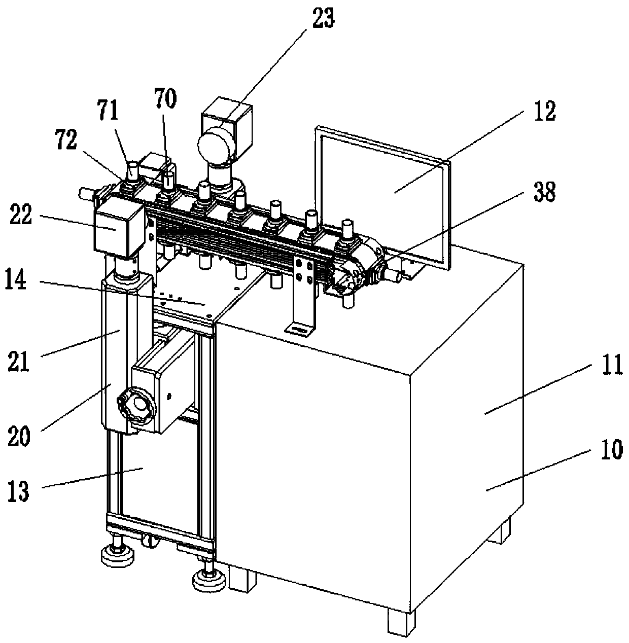
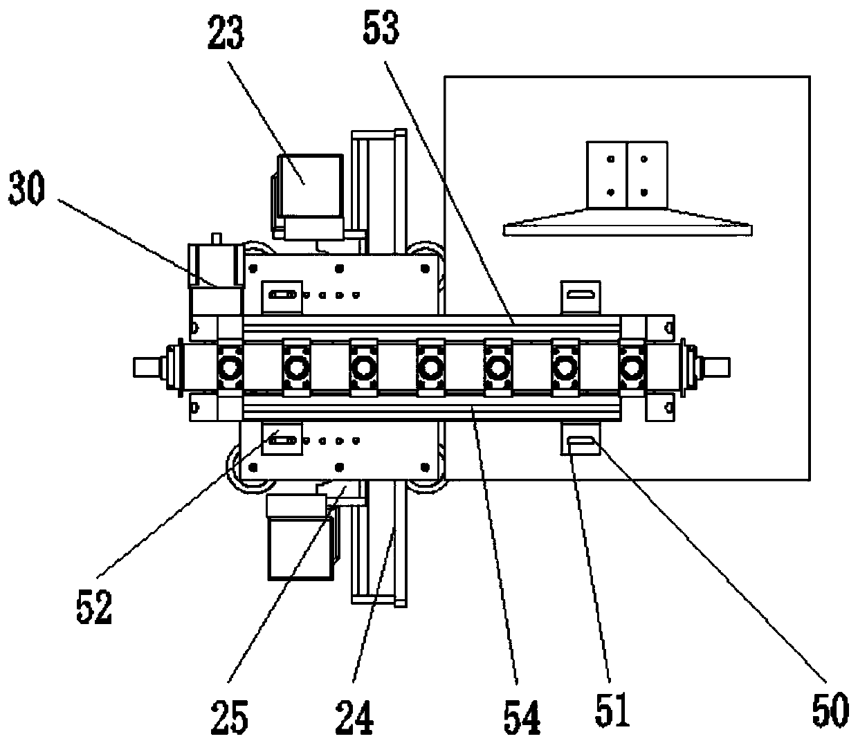
[0027] see Figure 1-5 , the present invention provides a technical solution: a laser laser printing device, comprising:

[0028] The main body assembly 10, the main body assembly 10 includes a first housing 11, a computer 12, a second housing 13, a plate body 14, a through groove 15 and a support assembly 40;

[0029] The printing assembly 20, the printing assembly 20 includes a fixed rod 21, a first laser 22, a second laser 23, a connecting piece 24 and a connecting plate 25, and both sides of the second housing 13 are provided with a fixed rod 21, and the two fixed rods 21 A first laser 22 and a second laser 23 are respectively installed on the top;

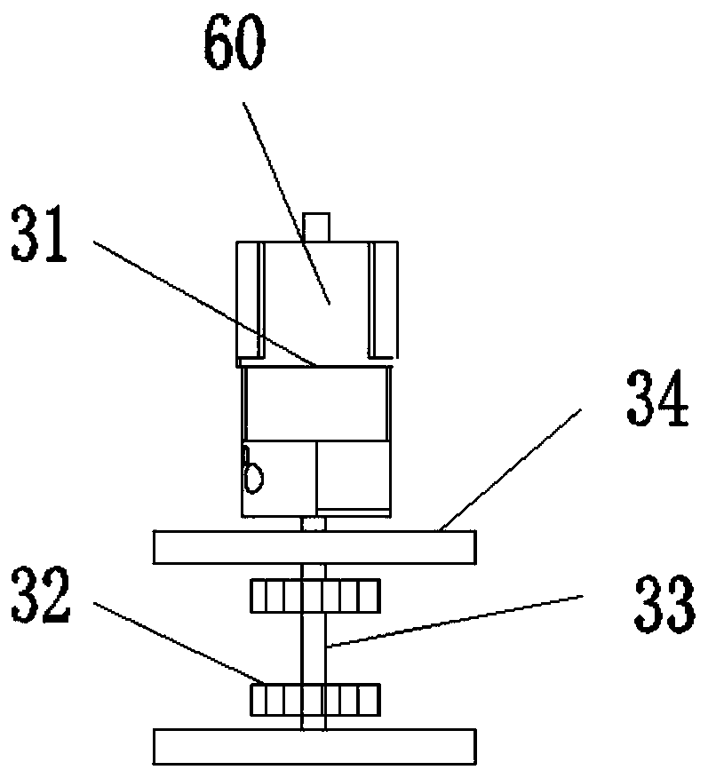
[0030] Drive assembly 30, drive assembly 30 comprises stepper motor 31, gear 32, rotating shaft 33, fixed plate 34, bearing 36, chain conveyer belt 37, conveyer frame 38 fixed assembly 50 and feeding assembly 70, one of the first housing 11 The side screw is connected with a stepper motor 31, and the two sides of the transpo...


PUM


Abstract

The invention discloses a laser printing device which comprises fixed rods, a first laser device, a second laser device, a connecting piece and a connecting plate. The fixed rods are arranged on the two sides of a second shell correspondingly. The first laser device and the second laser device are installed on the tops of the two fixed rods correspondingly. Through the cooperation of a stepping motor, a gear, a rotating shaft, bearings and a chain conveying belt, products are conveyed by the chain conveying belt to flow to a marking area to be marked, the chain conveying belt automatically moves forward by one position after marking is completed, marking is ceaselessly performed, and the taking actions of personnel are reduced. Jigs on fixed rotary clamps are designed through profiling, sothe products are fixed and positioned precisely; and the products flow to the marking area through the chain conveying belt, bidirectional marking is performed through the first laser device and thesecond laser device, each fixed clamp is independent, when the jigs move to the marking area, the jigs perform automatic clamping, and the ghosting caused by shaking of the products is reduced.

Description

technical field [0001] The invention relates to the field of laser technology, in particular to a laser printing device. Background technique [0002] Using laser beams to quickly "project" digital graphics or documents onto a photosensitive surface (photosensitive drum), use high-energy-density lasers to irradiate parts of the workpiece, and burn fonts by dissolving plastic at high temperatures. Laser lasers can print various Characters, symbols and patterns, etc., the character size can range from millimeters to microns, which is of special significance to the anti-counterfeiting of products. The output quality of laser printing is very high, and it truly realizes "what you see is what you get. The material reduces the production efficiency of the product. After the printing is completed, it is necessary to wait for the product to be placed before printing, which affects the low efficiency of laser printing and leads to low equipment utilization. Therefore, a laser laser p...

Claims


Application Information

Patent Timeline
Patent Type & Authority Applications(China)
IPC IPC(8): B23K26/362B23K26/02B23K26/70
CPCB23K26/02B23K26/362B23K26/702
Inventor 邵奎贤杨庆祥骆敏奇
Owner SHENZHEN MTC LUX CO LTD
Learn More