Efficient precise welding mold of belt type feeder guide groove
What is Al technical title?
Al technical title is built by PatSnap Al team. It summarizes the technical point description of the patent document.
A welding mold and feeder technology, applied in welding equipment, welding equipment, auxiliary welding equipment, etc., can solve the problems of low efficiency, inaccurate position, complicated process and so on
Active Publication Date: 2020-01-17
HUNAN AOFENG HEAVY IND
View PDF8 Cites 5 Cited by
Summary
Abstract
Description
Claims
Application Information
AI Technical Summary
This helps you quickly interpret patents by identifying the three key elements:
Problems solved by technology
Method used
Benefits of technology
Problems solved by technology
Usually, after finishing the machining of the holes on the connecting section, the drop hopper or the column, draw the position of each hole on the corresponding mounting surface of the guide chute, and then drill the holes on the bench drill. The process is complicated and the efficiency is low. The position is imprecise, the shape of the material guide groove is large, and a relatively large bench drill is required to drill holes on it
Method used
Image
Click on the blue label to locate the original text in one second.
Reading with bidirectional positioning of images and text.
Examples
Embodiment
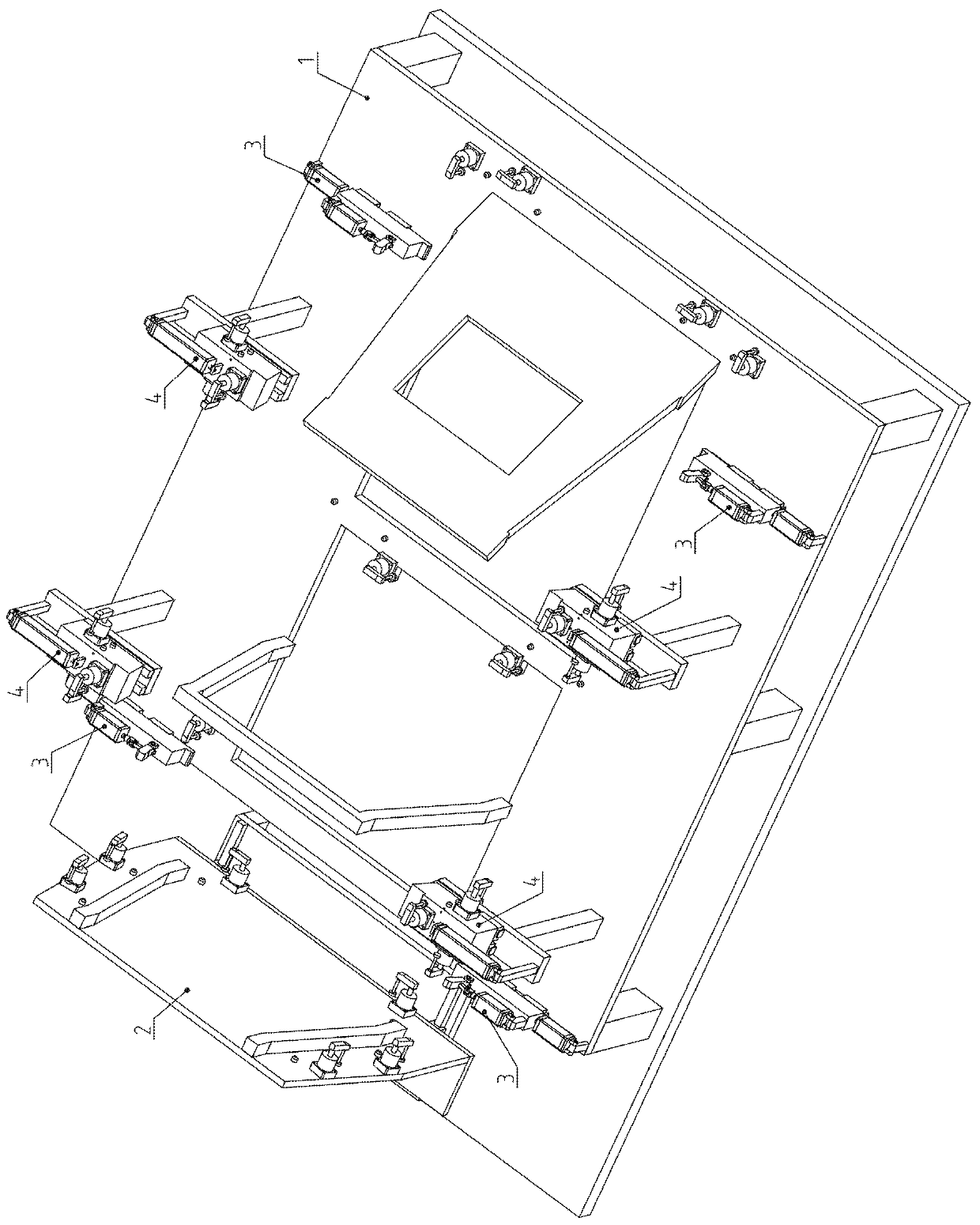
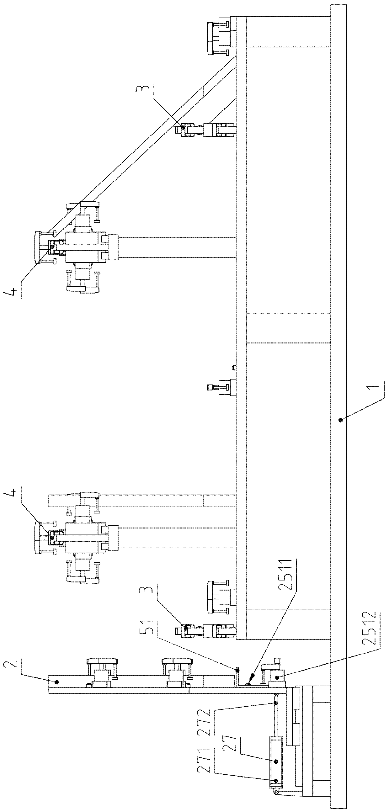
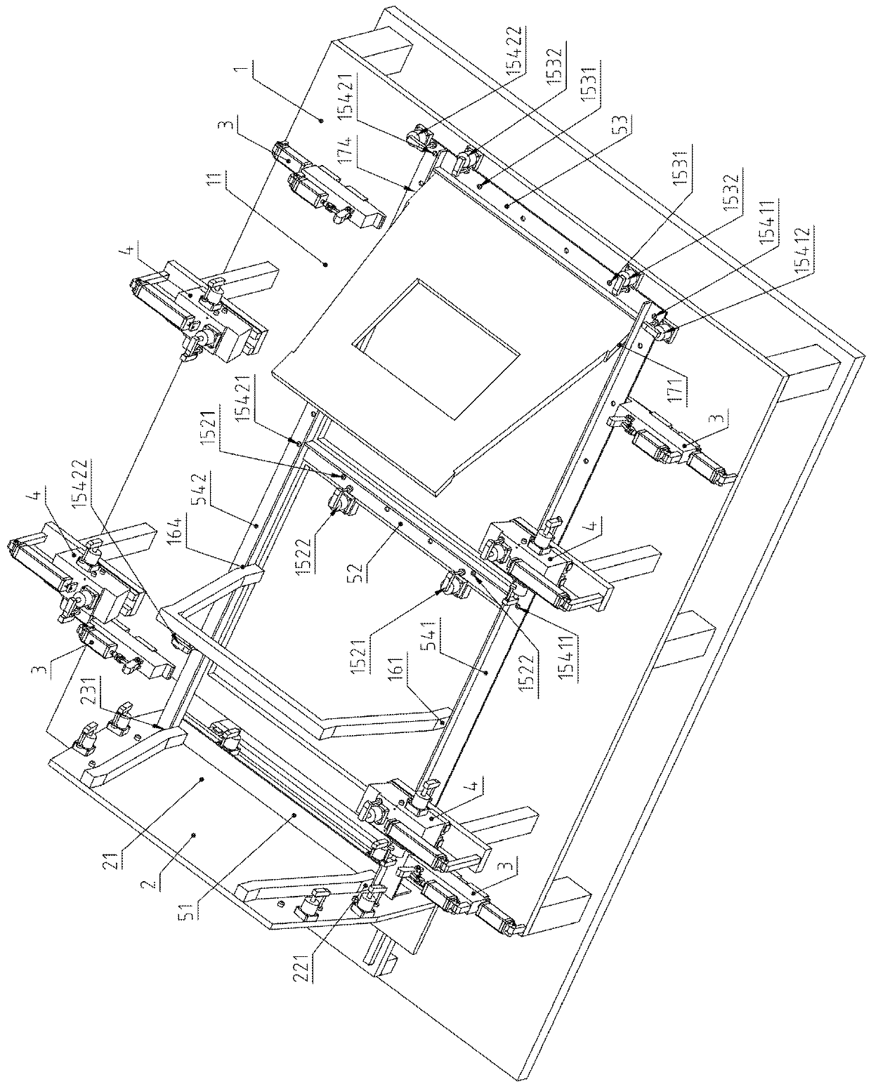
[0070] Example: see Figure 1 to Figure 16 .
[0071] A high-efficiency and precise welding mold for the guide groove of a belt feeder, including a base assembly 1, a front-end positioning assembly 2, four channel steel clamping assemblies 3 and four rib plate positioning assemblies 4;
[0072]The base assembly 1 is provided with a horizontal positioning surface 11 for locating the middle and lower angle steel 52, the rear lower angle steel 53, the lower left angle steel 541 and the lower right angle steel 542; the horizontal positioning surface 11 is provided with a front hole 111 and a rear hole 112. The hole 111 is located in front of the rear hole 112, and the welder stands in the front hole 111 or the rear hole 112 to perform welding, so as to weld the welding seam that is closer to the horizontal positioning surface 11 and faces downward; the rear hole 112 is surrounded by eight Locating pin; Two middle and lower angle steel locating pins 1521 which are positioned at th...
PUM
Abstract
The invention belongs to the technical field of mine machine manufacturing, and relates to an efficient precise welding mold of a belt type feeder guide groove. Front upper angle steel positioning pins carry out positioning, a front upper angle steel corner oil cylinder presses front lower angle steel, and a front end positioning assembly transversely moves backwards to finish positioning; angularsteel positioning pins position lower middle angle steel, lower rear angle steel, lower left angle steel and lower right angle steel which are compressed by angle steel corner oil cylinders; a groovesteel clamping assembly positions and clamps left groove steel and right groove steel; a rib plate positioning assembly positions and clamps long ribs, short ribs and flat plates; a left front flangeplate positioning pin positions a left front flange plate, and a left front flange plate corner oil cylinder carries out pressing; a right front flange plate positioning pin positions a right front flange plate, and a right front flange plate corner oil cylinder carries out compressing; and a rib plate positioning assembly positions and clamps left upper angle steel and right upper angle steel, and an upper angle steel corner oil cylinder carries out pressing. The produced guide groove is consistent in size, good in interchangeability, simple in process, high in work efficiency and small in used bench drill specification.
Description
technical field [0001] The invention belongs to the technical field of mining machinery manufacturing equipment, and relates to a manufacturing equipment for a belt feeder guide groove, in particular to an efficient and precise welding mold for a belt feeder guide groove. Background technique [0002] The guide groove of the belt feeder is often turned upside down during the assembly welding process, so that the workpiece after assembly welding has more upward welding seams, which is more convenient for welding. [0003] The guide groove includes front lower angle steel, middle lower angle steel, rear lower angle steel, left lower angle steel, right lower angle steel, left channel steel, right channel steel, left large plate, right large plate, left front flange plate, right front flange plate , left front long bar, left back long bar, right front long bar, right back long bar, left front short bar, left back short bar, right front short bar, right back short bar, left front...
Claims
Application Information
Patent Timeline
Application Date:The date an application was filed.
Publication Date:The date a patent or application was officially published.
First Publication Date:The earliest publication date of a patent with the same application number.
Issue Date:Publication date of the patent grant document.
PCT Entry Date:The Entry date of PCT National Phase.
Estimated Expiry Date:The statutory expiry date of a patent right according to the Patent Law, and it is the longest term of protection that the patent right can achieve without the termination of the patent right due to other reasons(Term extension factor has been taken into account ).
Invalid Date:Actual expiry date is based on effective date or publication date of legal transaction data of invalid patent.