A foamed plastic tray coated with wear-resistant coating
A wear-resistant coating and foaming plastic technology, applied in rigid containers, containers, packaging, etc., can solve the problems of tray deformation, poor impact resistance, and reduced stability of tray operation, so as to facilitate installation and disassembly, and improve durability. Grinding performance, avoiding even cracking effect
- Summary
- Abstract
- Description
- Claims
- Application Information
AI Technical Summary
Problems solved by technology
Method used
Image
Examples
Embodiment example 1
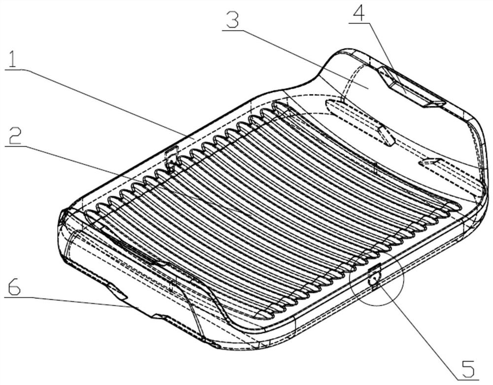
[0032] Example 1: A foamed plastic tray coated with a wear-resistant coating, including a core 1 and a surface wear-resistant coating 2, the core 1 is made of foamed plastic, and the material of the core 1 includes but is not limited to foam Hard foamed plastics such as hard PU, foamed PP, foamed PVC, EPP, etc., the outside of the core 1 is coated with a surface wear-resistant coating 2, and the material of the surface wear-resistant coating 2 includes but is not limited to polyurea coating, wear-resistant polyurethane, etc. A chip 9 is arranged inside the core 1 , a chip fixing structure 5 is arranged on the core 1 , and a V-shaped stacking structure 3 is arranged at both ends of the tray.
Embodiment example 2
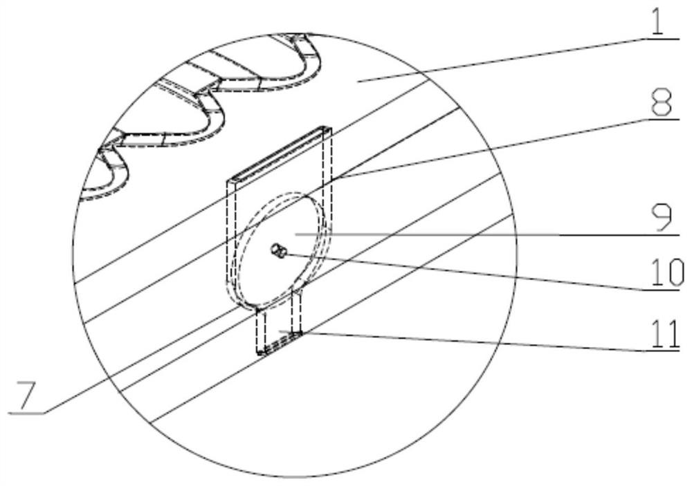
[0033] Implementation Case 2: If figure 2 As shown, this implementation is further optimized on the basis of Embodiment 1. This embodiment focuses on the improvements compared with Embodiment 1, and the similarities will not be repeated. The chip 9 is symmetrically arranged on the core 1 , the chip fixing structure 5 includes a mounting groove 8, a fixing protrusion 10 and a jacking groove 11, the chip 9 is installed in the mounting groove 8, the fixing protrusion 10 is symmetrically arranged and snapped in the middle of the chip 9, and the fixing protrusion 10 is fixed In the installation groove 8, the fixing protrusions 10 are symmetrically clamped on both ends of the chip 9 to ensure that there is no direction restriction when the chip 9 is running. , The contact between the mounting groove 8 and the chip 9 adopts the arc portion 7 matching the chip 9 to improve the stability of the chip 9 when it is installed.
Embodiment example 3
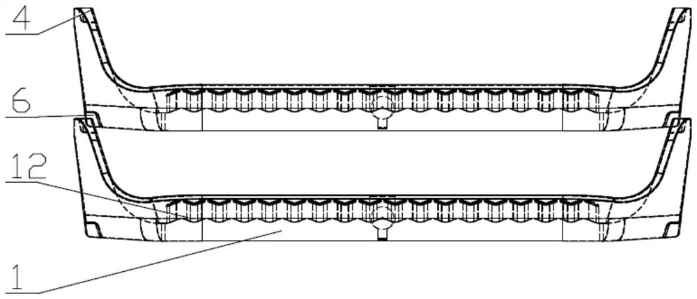
[0034] Implementation case three: if image 3As shown, this implementation is further optimized on the basis of Embodiment 1. This embodiment focuses on the improvements compared with Embodiment 1, and the similarities will not be repeated. The V-shaped stacking structure 3 includes V-shaped groove 4 and V-shaped protrusion 6, the upper side of the tray is recessed to form a V-shaped groove 4, and the lower side of the adjacent tray protrudes downward to form a V-shaped protrusion that matches the V-shaped groove 4 6. The core 1 is provided with reinforcing ribs 12 on the side where the luggage is placed.
PUM
 Abstract
Description
Claims
Application Information
 - R&D
- Intellectual Property
- Life Sciences
- Materials
- Tech Scout
- Unparalleled Data Quality
- Higher Quality Content
- 60% Fewer Hallucinations
Browse by: Latest US Patents, China's latest patents, Technical Efficacy Thesaurus, Application Domain, Technology Topic, Popular Technical Reports.
© 2025 PatSnap. All rights reserved.Legal|Privacy policy|Modern Slavery Act Transparency Statement|Sitemap|About US| Contact US: help@patsnap.com


