HDPE water supply pipe machining conveying device

A technology for conveying devices and water supply pipes, applied in the direction of conveyors, mechanical conveyors, conveyor objects, etc., can solve the problems of reducing friction and not being able to convey with different sizes and radii, and achieve reduced friction and good clamping effect , strong applicability

Active Publication Date: 2020-01-17
安庆市悦发管业有限公司
View PDF7 Cites 21 Cited by
  • Summary
  • Abstract
  • Description
  • Claims
  • Application Information

AI Technical Summary

Problems solved by technology

[0004] The purpose of the present invention is to provide a processing and conveying device for HDPE water supply pipes. Two transmission mechanisms are arranged above the support base, the first connecting ear is fixedly installed on the bottom of the transmission mechanism, and the first threaded rod is driven by starting the first motor. Rotate, so as to drive the two transmission mechanisms to clamp the HDPE water supply pipe, and drive the transmission belt to rotate by starting the two transmission motors, thereby driving the HDPE water supply pipe to move. During the movement of the HDPE water supply pipe, the support roller at the bottom follows Rotation greatly reduces friction. The conveying device can adjust the distance between the two conveying mechanisms according to different sizes of HDPE water supply pipes. It has strong applicability and solves the problem that the existing conveying device cannot convey different sizes of radii. technical problems;

Method used


Image

  • HDPE water supply pipe machining conveying device
  • HDPE water supply pipe machining conveying device
  • HDPE water supply pipe machining conveying device

Examples


Embodiment Construction

[0031] The technical solutions of the present invention will be clearly and completely described below in conjunction with the embodiments. Apparently, the described embodiments are only some of the embodiments of the present invention, not all of them. Based on the embodiments of the present invention, all other embodiments obtained by persons of ordinary skill in the art without creative efforts fall within the protection scope of the present invention.

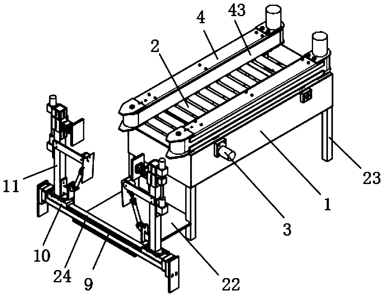
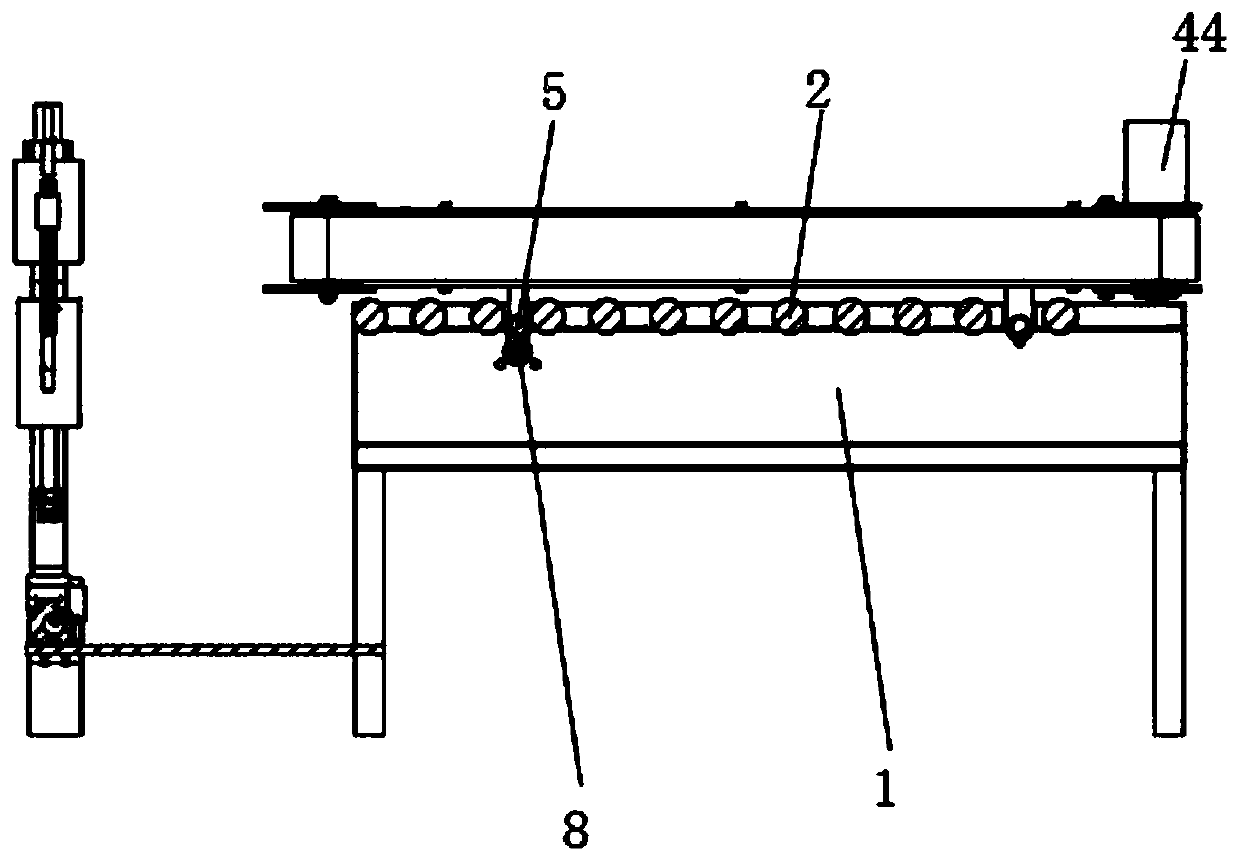
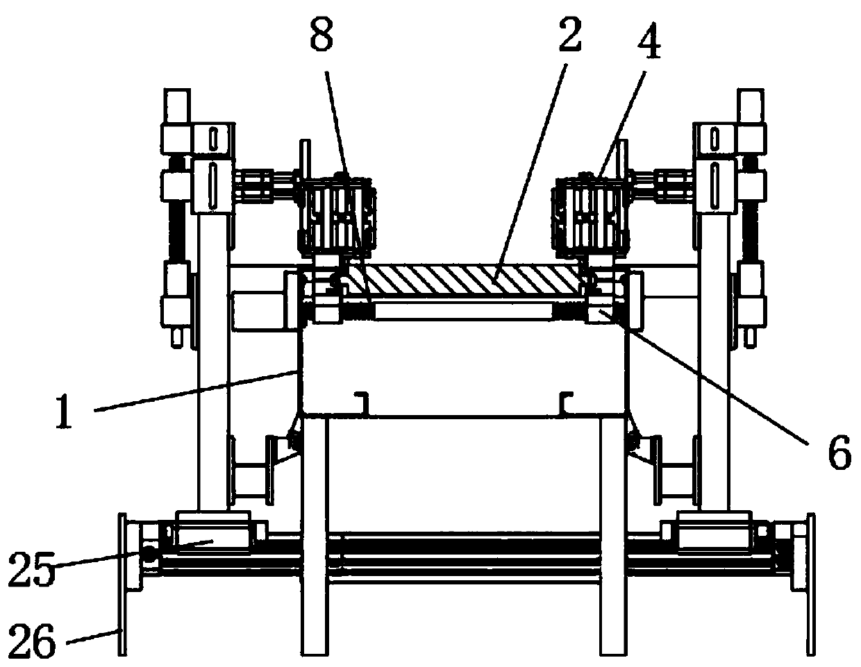
[0032] Such as Figure 1-5As shown, a HDPE water supply pipe processing and conveying device includes a support base 1, the support base 1 is a cuboid structure that runs through the upper and lower sides, and two transmission mechanisms 4 are arranged above the support base 1. The transmission mechanism 4 is symmetrically distributed, and several support rollers 2 are arranged on the inner side of the support seat 1;

[0033] Described transmission mechanism 4 comprises top plate 41 and bottom plate 46 that are distribute...


PUM


Abstract

The invention discloses an HDPE water supply pipe machining conveying device. The device comprises a supporting base, two conveying mechanisms are arranged above the supporting base, each conveying mechanism comprises a top plate and a bottom plate which are distributed up and down, two transmission wheels are arranged between each top plate and the corresponding bottom plate, the outer sides of two transmission wheels are sleeved with a transmission belt, the bottom face of each bottom plate is fixedly provided with a first connecting lug and a second connecting lug, the inner side of the supporting base is provided with a first thread rod, and the first thread rod is in threaded connection with the first connecting lugs. The conveying device can adjust the distance between the two conveying mechanisms according to the different sizes of HDPE water supply pipes, adaptation is high, and conveying of the HDPE water supply pipes of different sizes and radii can be met. The two conveyingmechanisms can be kept stable during moving, and the clamping effect on the HDPE water supply pipes is good. Through a supporting plate, supporting is provided for the HDPE water supply pipes, two fixed clamping plates move to clamp and the fix the HDPE water supply pipes, and during machining of the HDPE water supply pipes, stability is ensured.

Description

technical field [0001] The invention relates to the technical field of pipe processing equipment, in particular to an HDPE water supply pipe processing and conveying device. Background technique [0002] HDPE pipes are currently supplied to China's municipal pipe market. Plastic pipes are developing steadily. PE pipes, PP-R pipes, and UPVC pipes all occupy a place. Among them, the strong development momentum of PE pipes is the most eye-catching. PE pipes are used in a wide range of fields. Water supply pipes and gas pipes are its two largest application markets; [0003] The patent document (CN107187850A) discloses a pipeline conveying device, which outputs multiple pipelines at the same time. This pipeline conveying device has great limitations. The pipeline conveying device cannot transport long-dimensioned pipelines. It is impossible to carry out processing steps such as cutting while outputting the pipeline. At the same time, the pipeline cannot be kept stable during tr...

Claims


Application Information

Patent Timeline
IPC IPC(8): B65G15/14B65G47/22B65G23/22B65G37/00B65G13/04
CPCB65G13/04B65G15/14B65G23/22B65G37/00B65G47/22B65G2201/0276
Inventor 钱海波何伟李义正章鹤桥马刚
Owner 安庆市悦发管业有限公司
Why Eureka
Try Eureka