Modular portable rock mechanics parameter tester
A portable technology for rock mechanics parameters, applied to scientific instruments, using stable tension/pressure to test the strength of materials, instruments, etc., can solve the problems of long cycle and high cost, and achieve the effect of short cycle, low cost and simple operation
- Summary
- Abstract
- Description
- Claims
- Application Information
AI Technical Summary
Problems solved by technology
Method used
Image
Examples
Embodiment 1
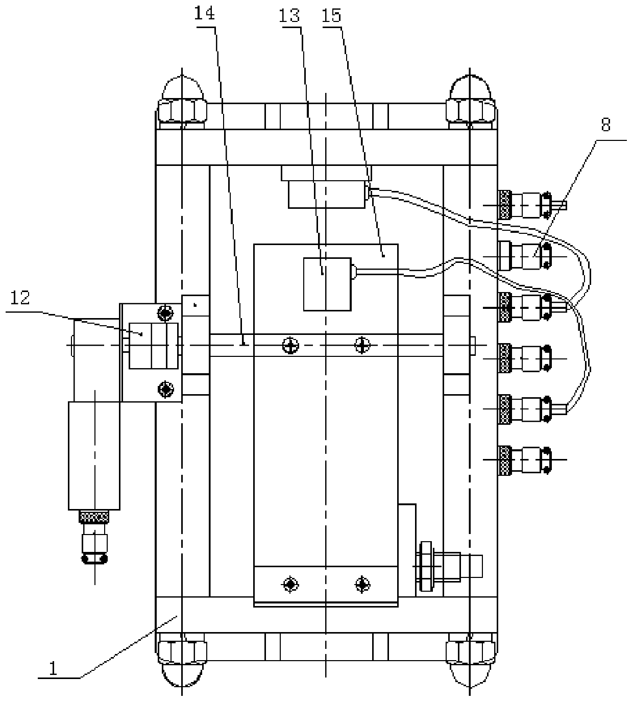
[0023] Embodiment 1: When performing rock friction angle testing, the drive motor 12 is connected to an external power supply to supply power to the drive motor 12, and the counterclockwise rotation of the drive motor 12 drives the rotating shaft 14 to rotate, and also drives the test piece supporting plate 15 to rotate. While looking at the angle value on the display screen, when the angle value shows 0 degrees, turn off the power switch, put two rock specimens on top of each other and put them on the front end of the specimen supporting plate 15, due to the weight of the rock specimen It may be that the angle value has a certain change, which can be readjusted to 0 degrees through the switch. After the adjustment is completed, the drive motor rotates clockwise by adjusting the switch. The moment the rock specimen slides and falls, turn off the power switch and record the angle value. The test is complete.
Embodiment 2
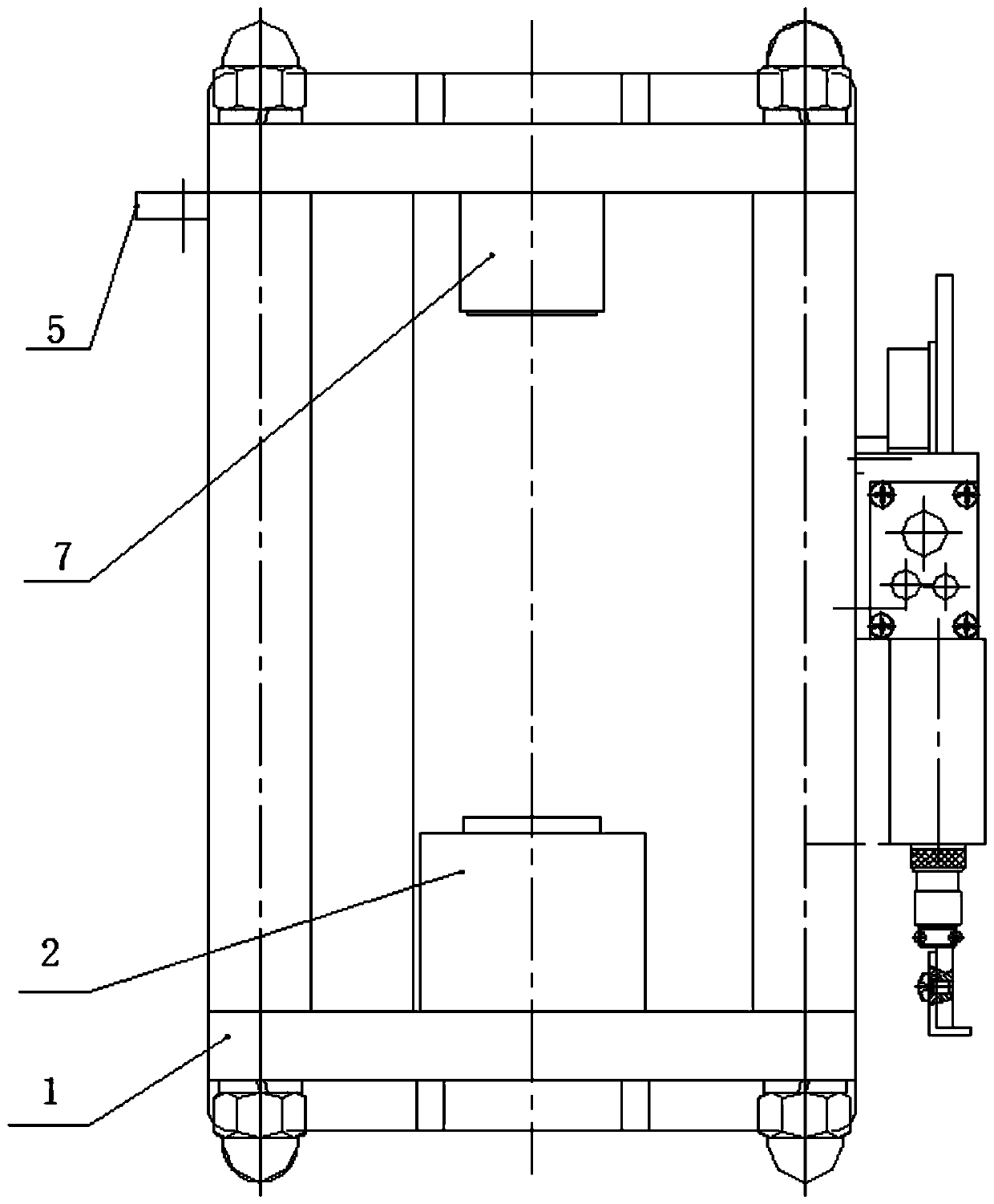
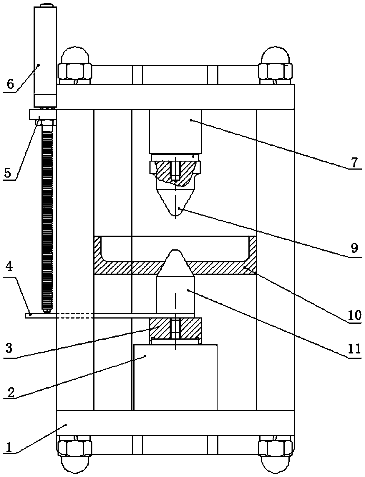
[0024] Embodiment 2: When carrying out the rock point load test, the driving motor 12, the rotating shaft 14 and the supporting plate in the embodiment 1 are removed, and then a certain pressure is applied by the hydraulic pump to make the piston rod in the jack 2 rise by a certain amount. Connect the centering block 3, the axial displacement transmission plate 4, and the lower pressure head 11 into a whole, and put the groove at the bottom of the centering block 3 on the piston rod of the jack 2, and adjust the linear displacement The probe at the lower part of the sensor 6 is in contact with the axial displacement transmission plate 4, and the crushing receiving plate 10 of the test piece is fixed on the lower pressing head 11 through the round hole in the middle, and then the point load test piece is placed on the upper pressing head 9 and the lower pressing head 9. In the middle of the head 11, apply a little pressure through the oil pump to make the upper pressure head 9 a...
Embodiment 3
[0025] Embodiment 3: Install the axial displacement transmission rod 4 on the rock triaxial test pressure chamber 16 to form a whole, and put the processed cylindrical test piece into the chamber of the rock triaxial test pressure chamber 16 , insert the upper and lower pressure heads, put the rock triaxial test pressure chamber 16 between the jack 2 and the pressure sensor 7, the upper and lower pressure rods are respectively connected to the jack and the pressure sensor 7, and the telescopic probe at the bottom of the linear displacement sensor 6 is adjusted to the The axial displacement transmission rod 4 is in contact. At this time, the hydraulic rod of the jack 2 slowly rises through the slow pressure applied by the oil pump, so that the upper pressure rod in the rock triaxial test pressure chamber 16 contacts the pressure sensor 7 and generates a certain pressure. At this time, a certain confining pressure is applied to the oil reservoir in the rock triaxial test pressure...
PUM
 Abstract
Description
Claims
Application Information
 - R&D
- Intellectual Property
- Life Sciences
- Materials
- Tech Scout
- Unparalleled Data Quality
- Higher Quality Content
- 60% Fewer Hallucinations
Browse by: Latest US Patents, China's latest patents, Technical Efficacy Thesaurus, Application Domain, Technology Topic, Popular Technical Reports.
© 2025 PatSnap. All rights reserved.Legal|Privacy policy|Modern Slavery Act Transparency Statement|Sitemap|About US| Contact US: help@patsnap.com


