Lens module

A lens module and lens technology, applied in the field of optical imaging, can solve the problems of complex lens module structure and lower production efficiency, and achieve the effects of simple structure, high production efficiency, anti-shake and auto-focus

Inactive Publication Date: 2020-01-17
AAC OPTICS (CHANGZHOU) CO LTD
View PDF8 Cites 15 Cited by
  • Summary
  • Abstract
  • Description
  • Claims
  • Application Information

AI Technical Summary

Problems solved by technology

[0003] The existing lens module uses an elastic suspension component to hang the lens component in the fixed frame, and the focusing coil and the magnetic steel arranged on one side cooperate to drive the lens component to move along the optical axis, so that the lens component is automatically moved in the fixed frame. Focusing; through the anti-shake coil and the magnetic steel set on one side, the lens assembly is driven to move along the vertical optical axis, and the shake of the lens assembly in the fixed frame is compensated; this setting makes the structure of the lens module complex, thereby reducing productivity

Method used


Image

  • Lens module
  • Lens module
  • Lens module

Examples


Embodiment Construction

[0031] The present invention will be further described below in conjunction with the accompanying drawings and embodiments.

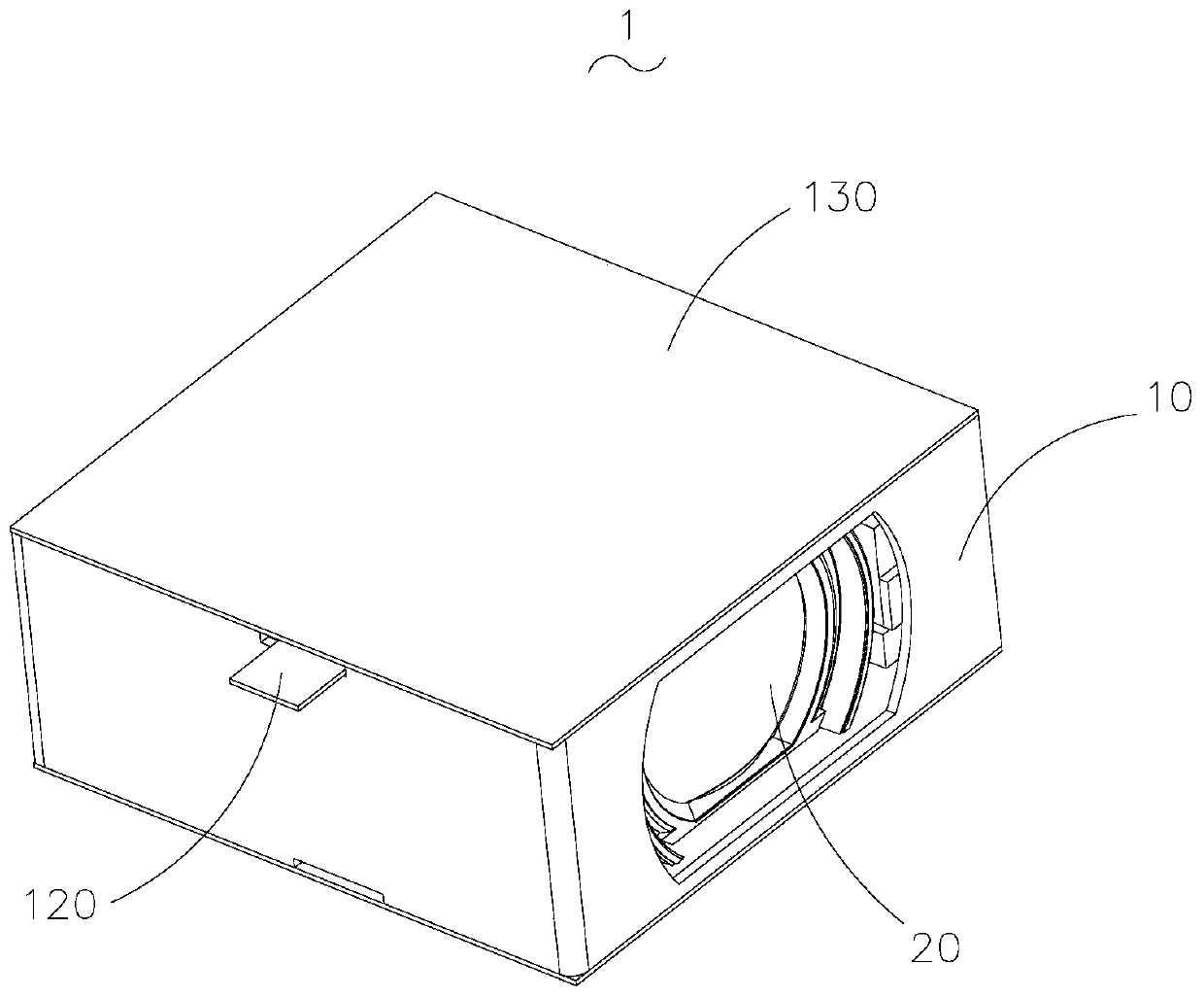
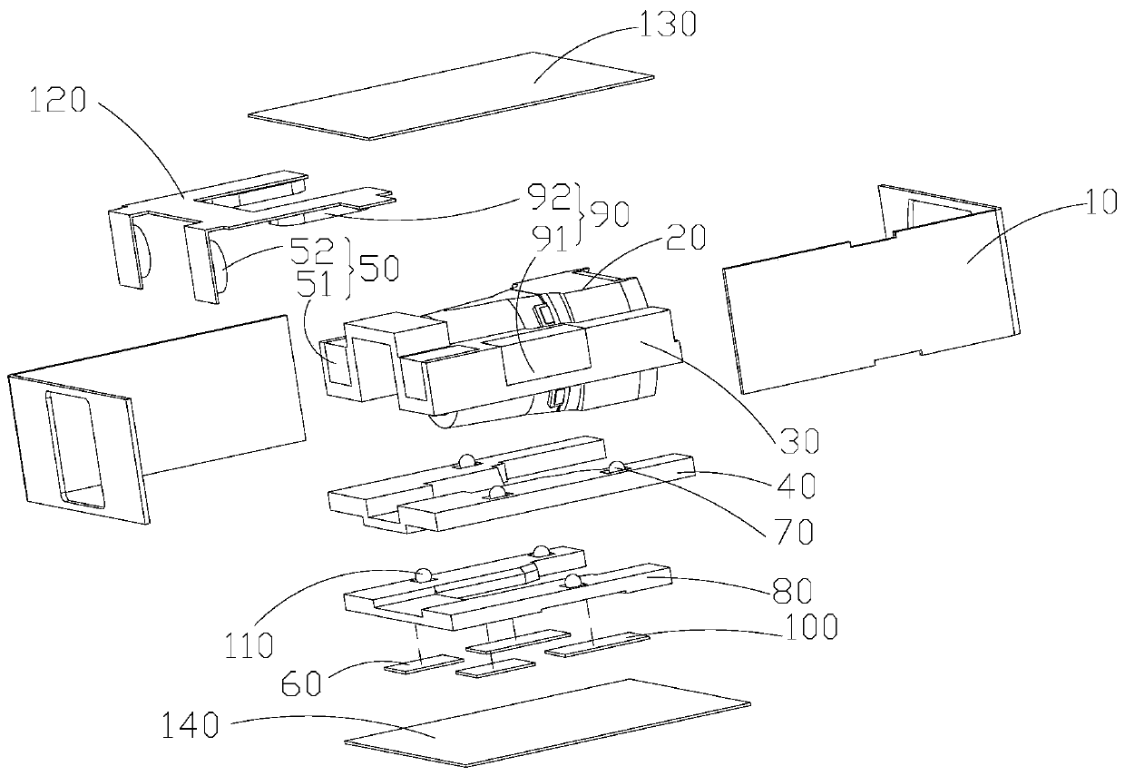
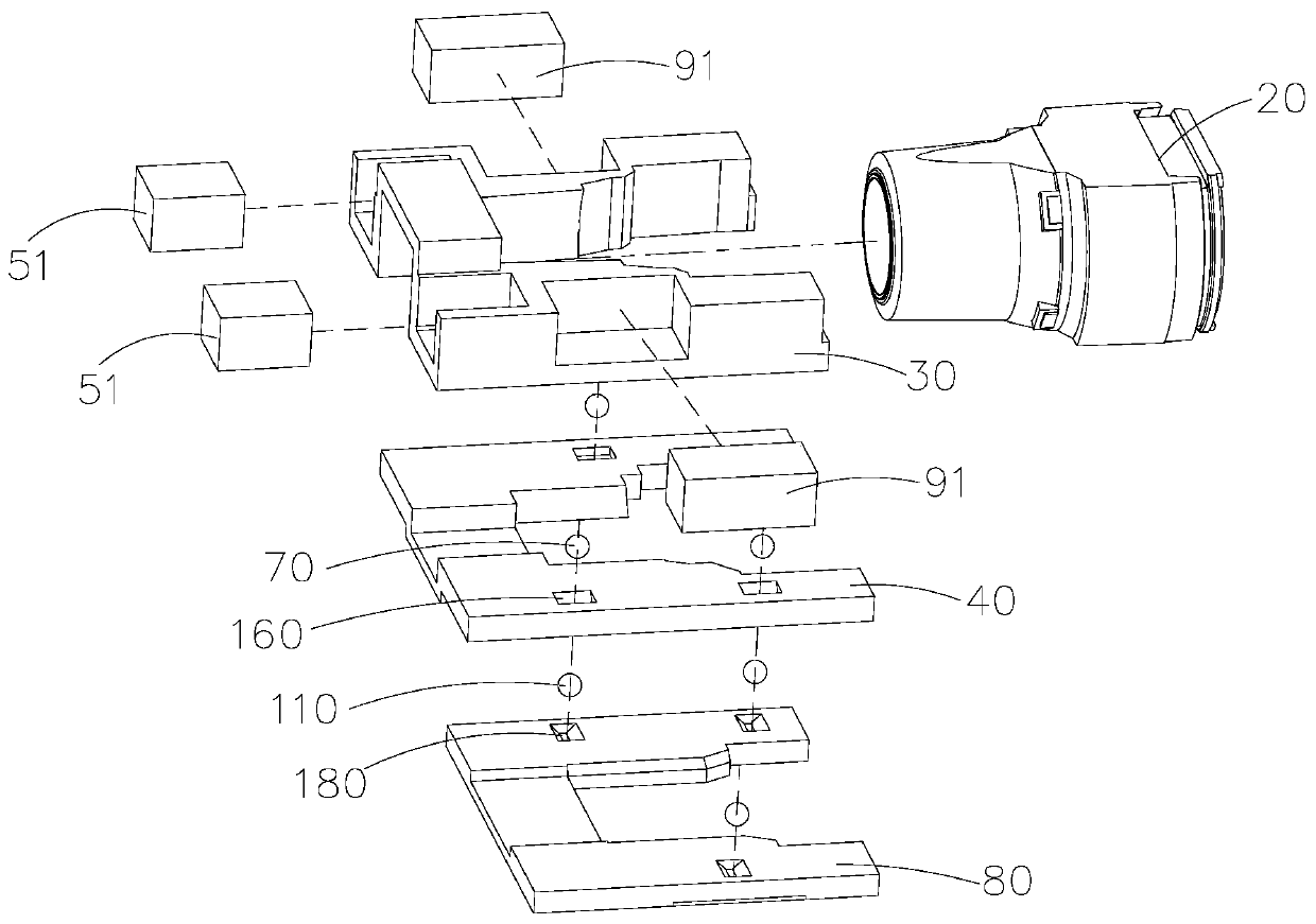
[0032] see Figure 1-7 , the first embodiment of the present invention relates to a lens module 1, comprising a housing, a lens 20 accommodated in the housing, a mounting bracket 30 for fixing the lens 20, a first base 40 opposite to the mounting bracket 30, a second Two bases 80, drive the mounting bracket 30 so that the lens 20 is relatively displaced relative to the first base 40 in the direction of the optical axis of the lens 20, and drive the mounting bracket 30 so that the lens 20 is relatively displaced relative to the second base 80 The relative displacement of the second driving member 90 in the direction perpendicular to the optical axis of the lens 20 , the first base 40 and the second base 80 are fixed relative to the housing. Specifically, the mounting bracket 30, the first base 40, and the second base 80 may be in sliding contact, so tha...


PUM


Abstract

The invention provides a lens module which comprises a shell, a lens accommodated in the shell, an installation support for fixing the lens, a first base and a second base which are arranged oppositeto the installation support, a first driving piece which drives the installation support to enable the lens to generate relative displacement in the optical axis direction of the lens relative to thefirst base, and a second driving piece which drives the installation support to enable the lens to generate relative displacement in the direction perpendicular to the optical axis direction of the lens relative to the second base. The first base and the second base are fixed relative to the shell. According to the invention, the lens is fixed by the installation support, and the lens is driven bythe first driving piece to generate the relative displacement along the optical axis direction, so that the lens is automatically focused in the shell; by driving the lens to generate the relative displacement along the direction vertical to the optical axis of the lens through the second driving piece, the jitter of the lens in the direction vertical to the optical axis is compensated, so that the lens module is simple in structure and high in production efficiency, and can effectively realize the anti-shake and automatic focusing.

Description

【Technical field】 [0001] The invention relates to the technical field of optical imaging, in particular to a lens module. 【Background technique】 [0002] In recent years, with the development of optical imaging technology and the rise of electronic products with imaging functions, optical lenses are widely used in various electronic products. Generally, light is directly incident from the object side, passes through the lens assembly along the optical axis to the image side, and forms an image of the object through the lens assembly. The lens assembly generally has an autofocusing function (autofocusing) and an optical image stabilization function (OIS: optical image stabilization). [0003] The existing lens module uses an elastic suspension component to hang the lens component in the fixed frame, and the focusing coil and the magnetic steel arranged on one side cooperate to drive the lens component to move along the optical axis, so that the lens component is automaticall...

Claims


Application Information

Patent Timeline
Patent Type & Authority Applications(China)
IPC IPC(8): G03B13/36G03B5/00G02B7/09G02B27/64
CPCG03B13/36G03B5/00G02B7/09G02B27/646G02B7/08G02B7/02
Inventor 李林珍卢继亮李刚张晋顾春欣
Owner AAC OPTICS (CHANGZHOU) CO LTD
Why Eureka
Try Eureka