Thermometer code to binary code circuit for time-to-digital converter

A thermometer code and binary code technology, applied in the field of decoding circuits, can solve the problems of occupying trigger resources, poor timing characteristics of the decoder, complex decoding algorithms, etc., to achieve improved accuracy and speed, good timing characteristics, and improved decoding. The effect of code speed

Active Publication Date: 2021-02-26
天津天芯微系统集成研究院有限公司
View PDF10 Cites 0 Cited by
  • Summary
  • Abstract
  • Description
  • Claims
  • Application Information

AI Technical Summary

Problems solved by technology

The thermometer code-to-binary code circuit described in this document can better filter the "bubbling" code segment of the thermometer code, but its decoding algorithm is complex, the utilization rate of FPGA resources is not high, and the decoding time is long
At the same time, the timing characteristics of the decoder described in this document are poor, and the pipeline structure can eliminate the timing problem caused by too much delay in the logic path, which takes up more flip-flop resources

Method used


Image

  • Thermometer code to binary code circuit for time-to-digital converter
  • Thermometer code to binary code circuit for time-to-digital converter
  • Thermometer code to binary code circuit for time-to-digital converter

Examples


Embodiment 1

[0029] 1. The thermometer code conversion binary code circuit designed by the present invention includes two parts: a LUT screening circuit and a RAM storage circuit.

[0030] Among them, the LUT screening circuit is used to identify the position where the highest bit 01 alternates, and filter the bubbling code segment of the thermometer code; the RAM storage circuit is used to pre-store the binary number, and realize the thermometer code to the binary code by reading the binary number pre-stored in the RAM. convert.

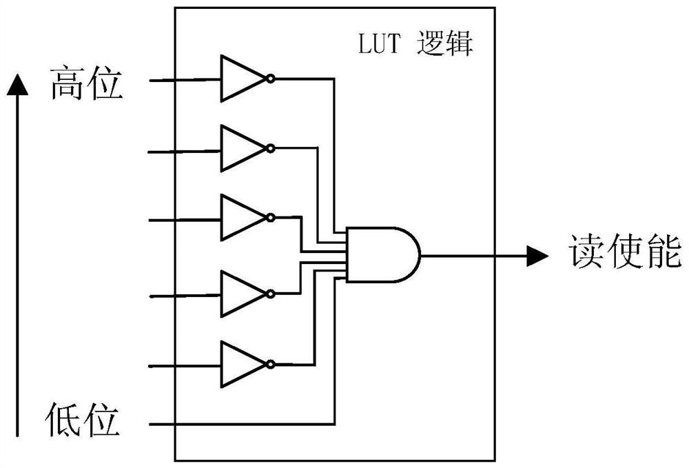
[0031] 2. In the present invention, the thermometer code is used as an input signal to be connected to the LUT screening circuit. The LUT unit in the screening circuit first inverts the upper 5 bits of the input signal, and then ANDs the inversion result with the lowest bit of the input signal to obtain an output signal, and uses the output signal as a control signal to be connected to the read driver of the RAM storage circuit. Capable.

[0032] 3. Before the...

Embodiment 2

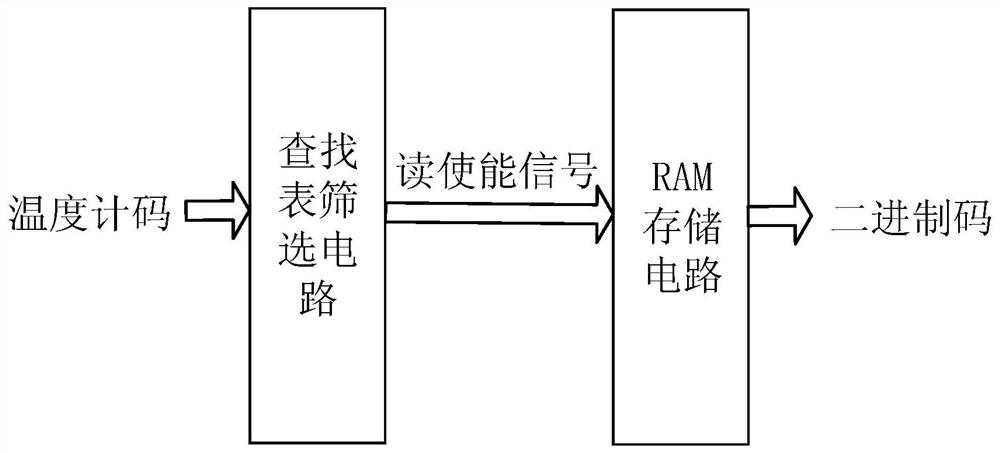
[0034] figure 1 The schematic diagram of the circuit for converting thermometer code to binary code. The circuit mainly includes two parts: LUT screening circuit and RAM storage circuit. The function of the former is to filter the bubbling code segment in the thermometer code, and the function of the latter is to convert the thermometer code into binary code.

[0035] The specific process is: first, input the thermometer code into the LUT screening circuit, "filter" out the "bubbling code segment" through logical operation, and output the read enable signal. Then, input the read enable signal into the RAM storage circuit, control Read out the binary code to complete the decoding process.

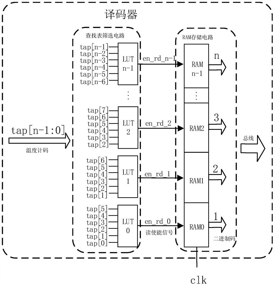
[0036] figure 2 It is the structure diagram of the thermometer code to binary code circuit. The LUT screening circuit consists of LUT resources in the FPGA. The essence of the LUT is a SRAM with 6-bit address lines, a depth of 64, and a bit width of 1 bit. It can realize the combinatio...


PUM


Abstract

The invention discloses a circuit for converting a thermometer code into a binary code circuit for a time-to-digital converter. The circuit comprises: a LUT screening circuit and an RAM storage circuit, the thermometer code is used as an input signal, which is accessed to the LUT screening circuit, an LUT unit in the screening circuit performs negation on upper 5 bits of the input signal, adds a negation result to the lowest bit of the input signal to obtain an output signal, and accesses the output signal to a reading enable end of the RAM storage circuit as a control signal; and when the reading enable end is pulled up, the binary code in the corresponding RAM storage circuit is read out at the next clock rising edge, so that the conversion of the thermometer code into the binary code isrealized. The circuit disclosed by the invention solves the bubbling problem existing in a decoding process of the time-to-digital converter based on FPGA, and improves the overall performance of theFPGA type time-to-digital converter.

Description

technical field [0001] The invention relates to the field of integrated circuit measurement, in particular to a decoding circuit used in an FPGA-based time-to-digital converter to convert thermometer codes into binary codes. Background technique [0002] Time interval measurement technology is of great significance to national economy and national defense industry construction. Accurate time interval measurement technology, especially picosecond (1ps=10 12 s) magnitude of technology is more important. Whether it is in theoretical research fields such as molecular biology, nuclear physics detection, or astronomical observation, or in engineering practice fields such as laser ranging, high-precision positioning, and food and drug safety monitoring, it has very important applications. [0003] At present, the most widely used high-precision time interval measurement technology is time-to-digital converter (TDC) technology, and its most important technical index is measurement ...

Claims


Application Information

Patent Timeline
Patent Type & Authority Patents(China)
IPC IPC(8): G04F10/00G01R31/28
CPCG01R31/2882G04F10/005
Inventor 谢生郭晓东
Owner 天津天芯微系统集成研究院有限公司
Why Eureka
Try Eureka