Forced air cooling disc type motor
A cold plate type and casing technology, which is applied in the field of forced air-cooled plate type motors, can solve the problems of increased copper and iron costs of the motor, increased motor capacity, and motor strikes, and achieves the effect of convenient application and improved heat dissipation
- Summary
- Abstract
- Description
- Claims
- Application Information
AI Technical Summary
Problems solved by technology
Method used
Image
Examples
Embodiment 1
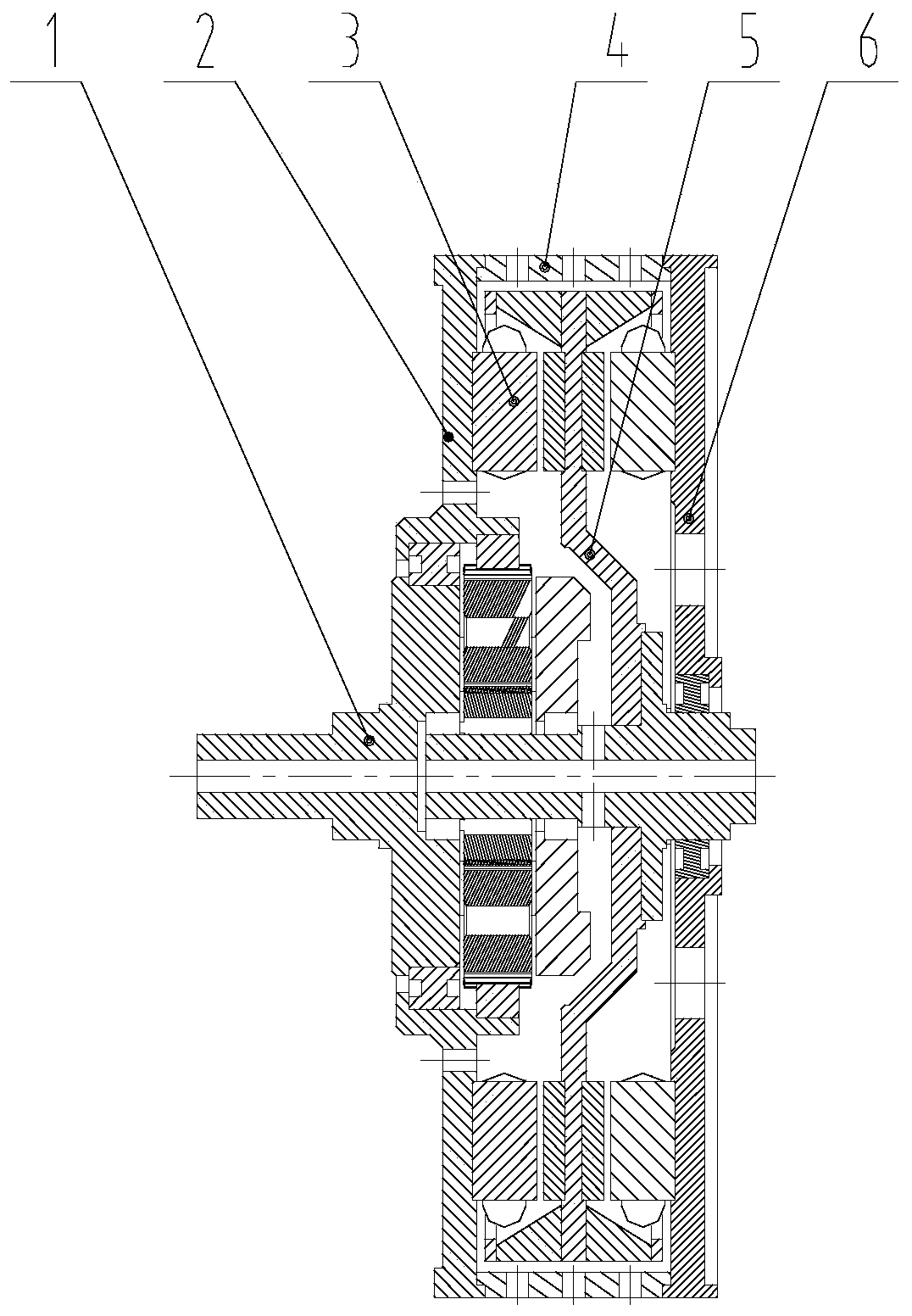
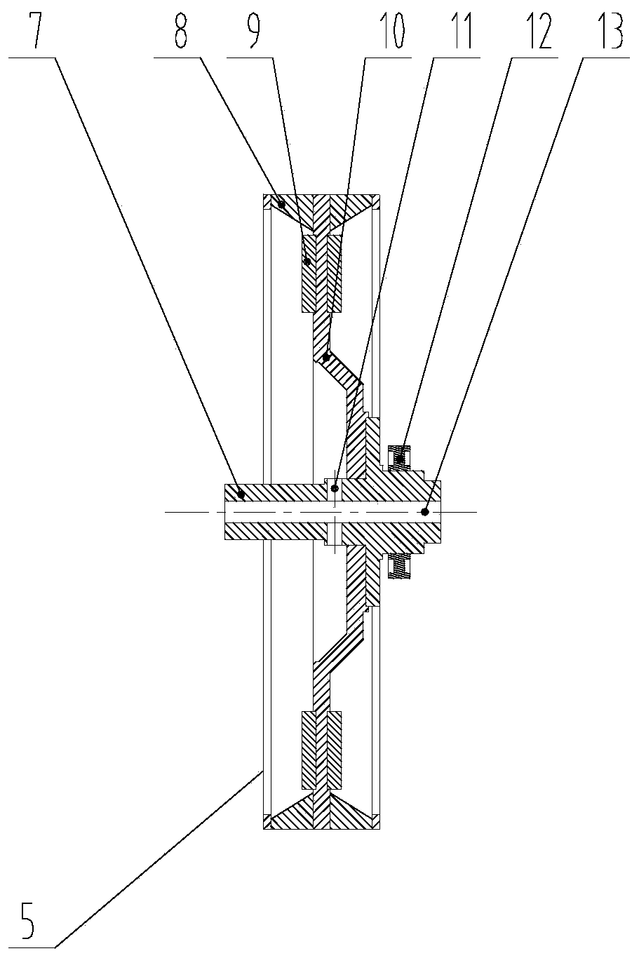
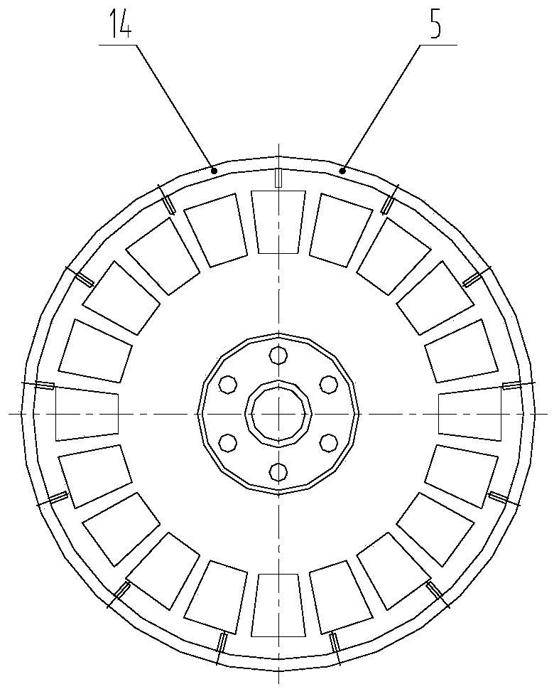
[0028] See Figure 1-6 with Figure 11 , a forced air-cooled disc motor, comprising a front cover 2, a casing 4 and a rear end cover 6, the casing 4 is a cylindrical structure, and the side wall of the casing 4 is uniformly provided with several air outlet holes 24, A front end cover 2 is installed on the left side of the casing 4, a rear end cover 6 is installed on the right side of the casing 4, and a rotor mechanism 5 matched with the rear end cover 6 is installed on the embedded middle part of the casing 4. The edge of the inner cavity of 4 is equipped with a stator mechanism 3 matched with the rotor mechanism 5, and the rotor mechanism 5 is connected to the rear end cover 6 through the rotation of the first bearing 12. The front end cover 2 is a ring plate structure, and the front end cover 2 The inner cavity of the inner cavity is connected with the planetary gear mechanism 1 matched with the rotor mechanism 5 through the second bearing 20. The front end cover 2 is prov...
Embodiment 2
[0030] See Figure 7-8 with Figure 11The difference from Embodiment 1 is that the planetary gear mechanism 1 includes a ring gear 15 and a planet carrier 18 matched with the rotating shaft 7, and the planet carrier 18 is rotatably connected to the front end cover 2 through the second bearing 20, and the planet carrier 18 is provided with a second ventilation hole 19 matched with the first ventilation hole 13, the axis of the second ventilation hole 19 coincides with the axis of the planet carrier 18, and the side end of the planet carrier 18 is provided with a ring gear 15, The middle part of the ring gear 15 is provided with a sun gear 17 matched with the planetary carrier 18, and several planetary gears 16 are evenly arranged between the sun gear 17 and the ring gear 15, and the ring gear 15 is far away from the planetary carrier 18. One end is covered with a cover plate 21 matching the rotating shaft 7. When the fan mechanism 14 is running, part of the air enters the plan...
Embodiment 3
[0032] See Figure 9-10 The difference from Embodiment 1 is that the stator mechanism 3 includes a left stator body 25 and a right stator body 27 respectively matched with the magnetic steel 9, and the left stator body 25 and the right stator body 27 are respectively installed on the front end cover 2 and the rear end cover 6, the left stator body 25 and the right stator body 27 are all provided with a stator slot 28, the stator slot 28 is equipped with a stator winding 26, after the whole device is energized, the magnetic steel 9 and the stator winding 26 The interaction generated by the magnetic field drives the rotor mechanism 5 to rotate, and further promotes the operation of the installed device, thereby completing the power output and its own air cooling, and the application is very convenient.
[0033] The working principle of Embodiment 1-3: after the whole device is energized, the interaction between the magnetic steel 9 and the magnetic field of the stator winding 26...
PUM
 Abstract
Description
Claims
Application Information
 - R&D
- Intellectual Property
- Life Sciences
- Materials
- Tech Scout
- Unparalleled Data Quality
- Higher Quality Content
- 60% Fewer Hallucinations
Browse by: Latest US Patents, China's latest patents, Technical Efficacy Thesaurus, Application Domain, Technology Topic, Popular Technical Reports.
© 2025 PatSnap. All rights reserved.Legal|Privacy policy|Modern Slavery Act Transparency Statement|Sitemap|About US| Contact US: help@patsnap.com


