
Parallel amplitude-phase calibration method and system for phased-array antenna

A phased array antenna and calibration method technology, applied in the field of antenna engineering, can solve the problems of high algorithm complexity, long calibration time, increased hardware cost, etc., and achieve the effects of low algorithm complexity, short calibration time, and high degree of parallelism

Active Publication Date: 2020-01-17
SHANGHAI SATELLITE ENG INST
View PDF4 Cites 7 Cited by
  • Summary
  • Abstract
  • Description
  • Claims
  • Application Information

AI Technical Summary

Problems solved by technology

Among them, the near-field method requires very complicated electromagnetic field measurement equipment, which is usually suitable for calibration inside the laboratory; the internal monitoring method requires additional hardware costs; the mid-field calibration method requires the position of the transmitting and receiving antenna to be in the mid-field interval, which is not suitable for medium and long distances calibration; the rotation vector method can usually only calibrate one unit at a time, and needs to traverse the state of each phase shifter, and the calibration time is longer; the commutation method has the problem of unstable inversion of the commutation matrix, and the algorithm complexity is also high; The four-phase amplitude calibration method proposed in the article has high requirements for the phase shift number and direction shift accuracy of the phased array antenna
[0004] In summary, the existing amplitude and phase calibration methods for active phased array antennas are either only suitable for laboratory or short-distance measurements, or there are problems such as low calibration efficiency, complex algorithms, and high hardware dependence.

Method used


Image

  • Parallel amplitude-phase calibration method and system for phased-array antenna
  • Parallel amplitude-phase calibration method and system for phased-array antenna
  • Parallel amplitude-phase calibration method and system for phased-array antenna

Examples


Embodiment Construction

[0047] The present invention will be described in detail below in conjunction with specific embodiments. The following examples will help those skilled in the art to further understand the present invention, but do not limit the present invention in any form. It should be noted that those skilled in the art can make several changes and improvements without departing from the concept of the present invention. These all belong to the protection scope of the present invention.

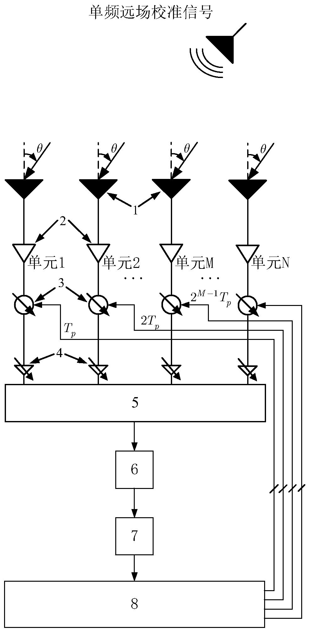
[0048] A parallel amplitude and phase calibration method for a phased array antenna provided according to the present invention, comprising:

[0049] Calibration signal setting steps: set the single-frequency calibration signal to be incident on the phased array antenna, or sent through the phased array antenna;

[0050] Initial state setting step: select multiple antenna units on the phased array antenna, and set the phase shifter of each selected antenna unit to the initial state;

[0051] Modulation...


PUM


Abstract

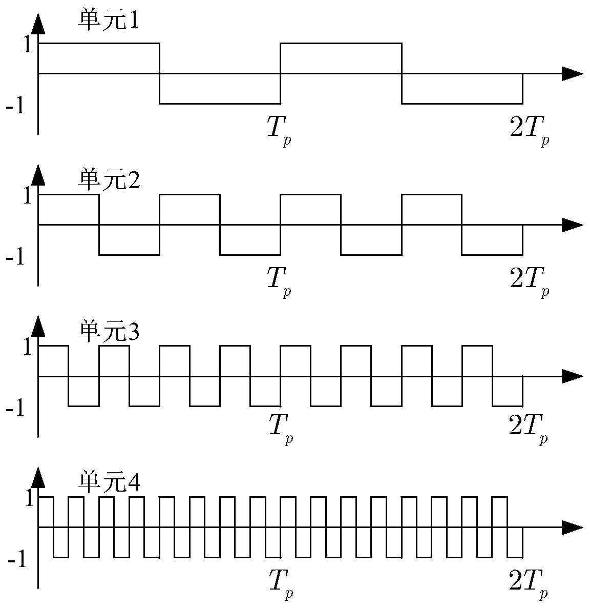
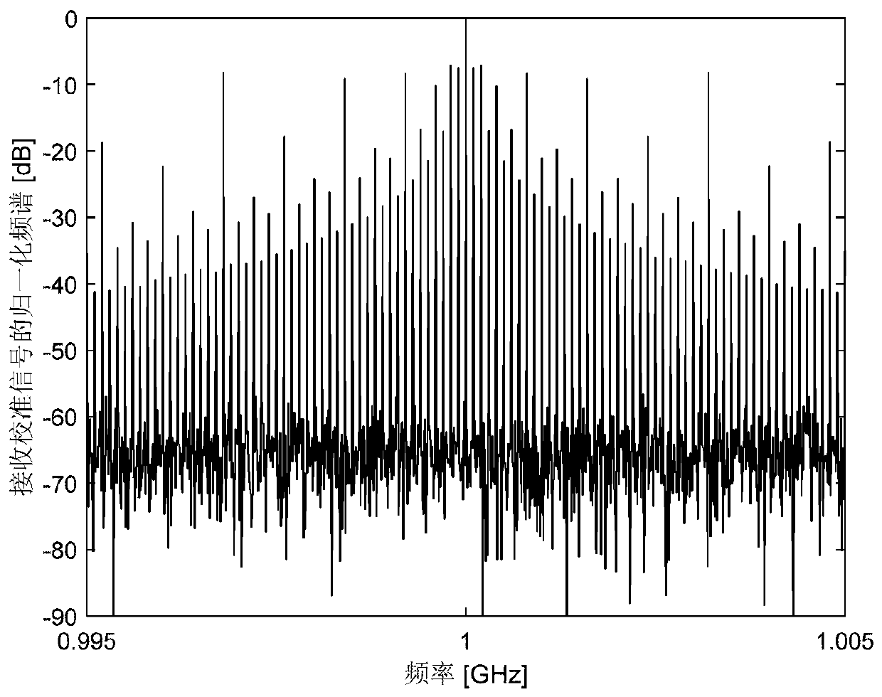
The invention provides a parallel amplitude-phase calibration method and a parallel amplitude-phase calibration system for a phased-array antenna. The method comprises a calibration signal setting step: setting a single-frequency calibration signal to be incident on the phased-array antenna, or to be transmitted through the phased-array antenna; an initial state setting step: selecting a pluralityof antenna units on the phased-array antenna, and setting the phase shifter of each selected antenna unit to be in an initial state; a modulation step: carrying out periodic phase modulation on the phase shifter of each selected antenna unit; and an analysis step: analyzing the harmonic characteristics of the received single-frequency calibration signal to calibrate the amplitude and phase of thecorresponding antenna unit. According to the invention, a plurality of units of the phased-array antenna can be simultaneously calibrated (the number of units calibrated at the same time is not limited), and the amplitude and the phase of each unit channel are calculated by carrying out harmonic characteristic analysis on the received calibration signal.

Description

technical field [0001] The invention relates to the technical field of antenna engineering, in particular to a parallel amplitude and phase calibration method and system for a phased array antenna. Background technique [0002] The active phased array antenna is composed of multiple units, and each unit contains multiple circuit units such as an antenna unit, a transceiver switch, a low noise amplifier, a power amplifier, a phase shifter, and a variable gain amplifier. Affected by various factors such as power supply, working environment, and component aging, the amplitude and phase of each unit of the phased array antenna will change. Therefore, when using an active phased array antenna, it is necessary to regularly or irregularly calibration. [0003] At present, the mainstream amplitude and phase calibration methods of active phased array antennas are compared in "Quick Calibration Methods for Phased Array Antennas" written by Wang Huanju et al., including near-field met...

Claims


Application Information

Patent Timeline
Patent Type & Authority Applications(China)
IPC IPC(8): H04B17/12H04B17/21
CPCH04B17/12H04B17/21
Inventor 曹岸杰贺冲陈靖峰范凯曲耀斌张国强成飞
Owner SHANGHAI SATELLITE ENG INST
Learn More