Panoramic video transmission method and system based on node calculation

A panoramic video and transmission method technology, which is applied in the field of node computing and video processing, can solve problems such as user experience impact and complexity, achieve the effects of reducing bandwidth overhead, reducing processing delay, and improving consumer experience

Inactive Publication Date: 2020-01-17
SHANGHAI JIAO TONG UNIV
7 Cites 2 Cited by

AI-Extracted Technical Summary

Problems solved by technology

The process of splicing is relatively complicated, and in the case of limited local processor capacity, it will of...

Method used

[0067] In the redundant transmission, the transmission decision module further includes: encoding and transmitting the user field of view area...

Abstract

The invention provides a panoramic video transmission method and system based on node calculation. The method comprises the following steps: obtaining feedback information of a user terminal in real time through an intermediate node, calculating a user visual field region according to the user visual field information, selecting a video stream accommodating the user visual field region for splicing, and obtaining a processed video stream; selecting a transmission scheme according to the user network condition information, extracting a transmission area for the processed video stream, and transmitting the transmission area code to a corresponding user terminal; wherein the transmission scheme comprises non-redundancy transmission and redundancy transmission, in the non-redundancy transmission, the transmission area is a user view area, in the redundancy transmission, the transmission area is a user view area plus a redundancy area, and the redundancy area is calculated according to usernetwork condition information and user terminal processing capability information. By combining the feedback information of the user terminal, the processing time delay can be effectively reduced, and the bandwidth overhead is reduced, so that the consumption experience of the user is integrally improved.

Application Domain

Technology Topic

Image

  • Panoramic video transmission method and system based on node calculation
  • Panoramic video transmission method and system based on node calculation
  • Panoramic video transmission method and system based on node calculation

Examples

  • Experimental program(1)

Example Embodiment

[0042] The present invention will be described in detail below with reference to specific embodiments. The following examples will help those skilled in the art to further understand the present invention, but do not limit the present invention in any form. It should be noted that, for those skilled in the art, several changes and improvements can be made without departing from the inventive concept. These all belong to the protection scope of the present invention.
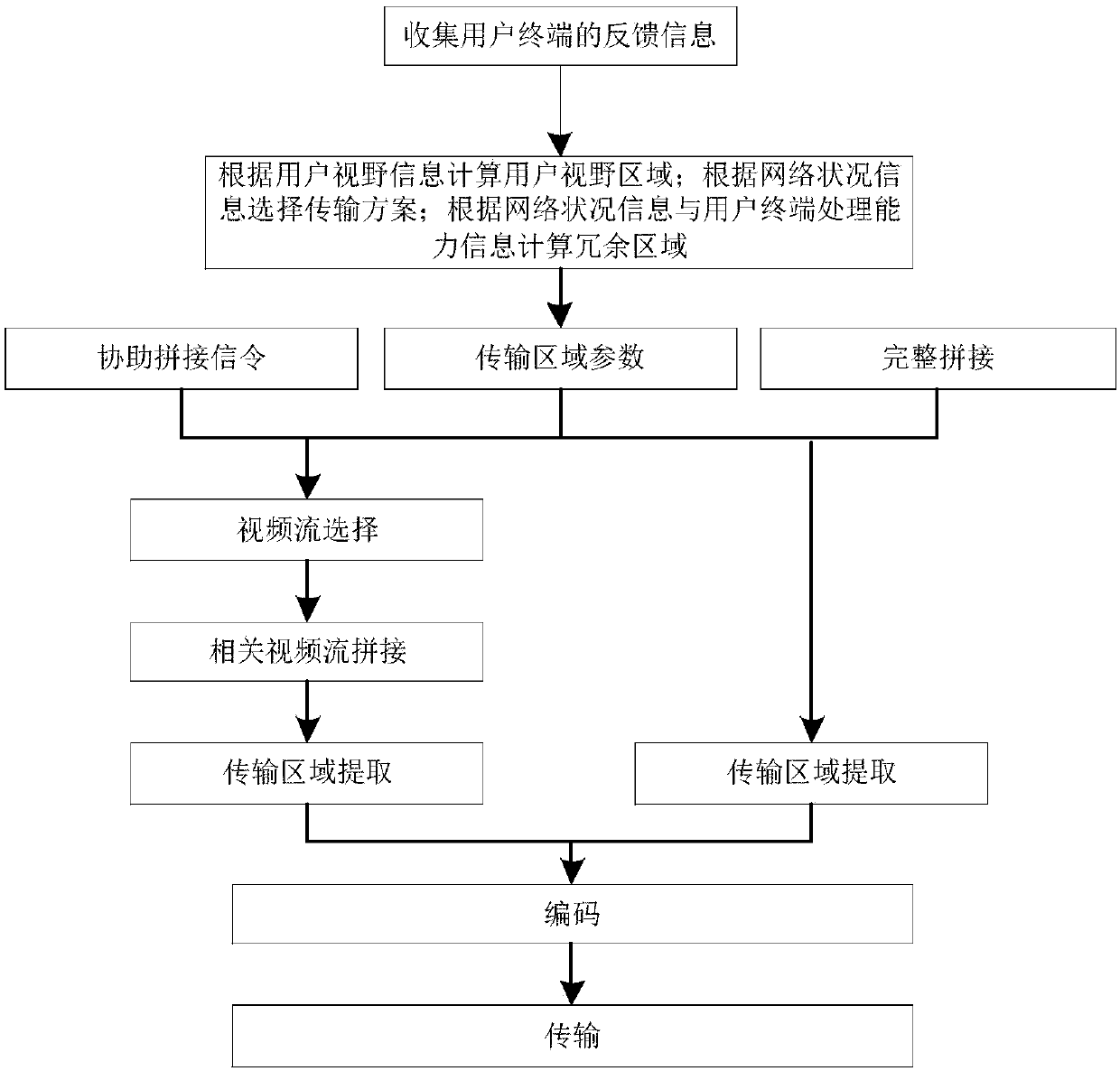
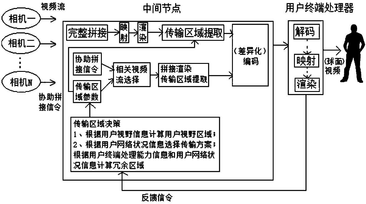
[0043] like figure 2 , image 3 As shown, a panoramic video transmission method based on node computing provided by the present invention includes an intermediate node, and the intermediate node executes:
[0044] The information acquisition step: acquire feedback information of the user terminal in real time, and the feedback information at least includes: user field of view information, user network status information and user terminal processing capability information;
[0045] Splicing step: calculating the user's visual field area according to the user's visual field information, selecting the video stream including the user's visual field area for splicing, and obtaining the processed video stream;
[0046] Transmission decision-making step: selecting a transmission scheme according to the user network status information, extracting a transmission area for the processed video stream, and transmitting the transmission area code to the corresponding user terminal;
[0047] The transmission scheme includes non-redundant transmission and redundant transmission. In non-redundant transmission, the transmission area is the user's field of view. In redundant transmission, the transmission area is the user's field of view plus the redundant area, and the redundant area is based on the user's network conditions. Information and user terminal processing capability information are calculated.
[0048] The transmission scheme of the present invention includes two transmission states of non-redundant transmission and redundant transmission, which does not conflict with the traditional full splicing method and can coexist.
[0049] No redundant transmission status: when the bandwidth is good, that is, when the transmission environment can quickly respond to changes in the user's field of view, the intermediate node calculates the user's field of view as the transmission area according to the user's field of view information, and then selects the video stream containing the user's field of view for splicing. , and intercept the transmission area, encode and transmit it to the user terminal for decoding and presentation, that is, a non-redundant transmission scheme.
[0050]Redundant transmission status: When the bandwidth situation is poor, that is, when the transmission environment cannot respond to the user's head action in time, a redundant transmission scheme based on the user's vision is adopted, which comprehensively considers the network bandwidth status, the user's vision information, and the processing capability of the user terminal. Based on the feedback information of the user terminal, the optimal area to be transmitted is calculated, and the corresponding video stream is selected according to the optimal area for splicing, and the optimal area is used as the transmission area for transmission. Specifically, the user field of view area is calculated according to the user field of view information, and the redundant area is calculated according to the user network status information and the user terminal processing capability information. The video streams including the user field of view area and the redundant area are spliced ​​to obtain a processed video stream.
[0051] On the basis of the above redundant transmission state, in addition to transmitting the optimal area of ​​uniform coding, the intermediate node can also perform unequal quality coding on the user's field of view area and redundant area and transmit them to the corresponding user terminal, that is, reduce the coding of the redundant area. quality. The range of the optimal area is generally larger than the user field of view area, which can effectively avoid the loss of user field of view caused by network delay. After the user terminal receives the optimal area, further mapping and rendering needs to be performed, but because the amount of data is relatively small, it takes very little time.
[0052] In order to realize the above two splicing schemes, it is necessary to transmit the corresponding auxiliary splicing information to assist the intermediate node splicing when the camera transmits the video stream to the intermediate node. The auxiliary splicing information needs to include the following information:
[0053] A. Stream coverage CoverageRange information. Describes the position in the entire panorama of the region covered by the final imaging of the current video stream, and is angular range information including horizontal and vertical angle information. Through the preliminary comparison between the angle coverage and the user's field of view information, the camera stream involved in the user's field of view information can be quickly found for partial splicing.
[0054] B. Timestamp information. Describes the time of shooting the current video stream, and guides the splicing of the cloud server. Because there may be differences in the time when multiple video streams arrive at the cloud server, the spliced ​​content must be recorded at the same time, so timestamps are required to ensure synchronization.
[0055] C. Camera Matrix CameraMatrix information: When splicing, the content shot by different cameras needs to be mapped to the translation coordinate system, so the relevant parameters of the camera matrix need to be used. The camera matrix is ​​divided into two parts, the camera internal parameter matrix and the external parameter matrix. When performing panoramic stitching, the internal and external parameters of the camera can be calculated from the specific content of the first few frames of images, but in order to reduce the delay as much as possible, it is recommended to save the internal and external parameters of the camera in the information to assist stitching. The external parameters include the rotation matrix and translation matrix of the camera, which together describe how to convert the point from the world coordinate system to the camera coordinate system, the rotation matrix describes the direction of the coordinate axis of the world coordinate system relative to the camera coordinate axis, and the translation matrix describes the direction of the camera coordinate axis. The position of the spatial origin in the camera coordinate system; the internal parameters include the focal length and the transformation from the imaging plane coordinate system to the pixel coordinate system; the internal and external parameters are combined to obtain the camera matrix, which can be used to project the image captured by the camera. Transform to the same stitching in one coordinate system.
[0056] It should be noted that the above information is necessary information to assist the intermediate nodes in splicing, but is not limited to the above information.
[0057] In order to realize the judgment of redundant and non-redundant transmission schemes, the user terminal needs to send feedback information to the intermediate node, and the feedback information includes:
[0058] A. User field of view information: describe the location information of the video content currently watched by the user;
[0059] B. User network status information: describe the transmission status of the user's current network, including bandwidth and delay;
[0060] C. User terminal processing capability information: describe the computing capability of the user's local processor, including throughput, response time and cpu occupancy.
[0061] It should be noted that the above information is necessary information to assist the intermediate node in selecting the solution, but is not limited to the above information.
[0062] Based on the above-mentioned panoramic video transmission method based on node computing, the present invention also provides a panoramic video transmission system based on node computing, including an intermediate node, and the intermediate node includes:
[0063] Information acquisition module: acquire feedback information of the user terminal in real time, the feedback information at least includes: user field of view information, user network status information and user terminal processing capability information;
[0064] Splicing module: calculate the user's visual field area according to the user's visual field information, select the video stream including the user's visual field area for splicing, and obtain the processed video stream;
[0065] Transmission decision module: select the transmission scheme according to the user network status information, extract the transmission area for the processed video stream, and transmit the transmission area code to the corresponding user terminal;
[0066] The transmission scheme includes non-redundant transmission and redundant transmission. In non-redundant transmission, the transmission area is the user's field of view. In redundant transmission, the transmission area is the user's field of view plus the redundant area, and the redundant area is based on the user's network conditions. Information and user terminal processing capability information are calculated.
[0067] In the redundant transmission, the transmission decision module further includes: performing unequal quality encoding on the user field of view area and the redundant area and transmitting to the corresponding user terminal, that is, reducing the encoding quality of the redundant area.
[0068] In the feedback information, the user field of view information describes the location information of the video content currently watched by the user; the user network status information describes the transmission status of the user's current network, including bandwidth and delay; the user terminal processing capability information describes the computing capability of the user terminal, including throughput , response time and cpu usage.
[0069] The video stream before splicing is transmitted from the camera to the intermediate node. The video stream transmitted by each camera is transmitted as an independent video stream. The camera transmits the splicing assistance information while transmitting the video stream. The splicing assistance information includes:
[0070] Stream coverage: It is the angle range information including the horizontal angle information and the vertical angle information, which describes the position of the area covered by the current video stream when it is finally imaged in the entire panorama;
[0071] Timestamp: describes the time when the current video stream was captured;
[0072] Camera matrix: includes external parameters and internal parameters. The external parameters include the rotation matrix and translation matrix of the camera. The rotation matrix and translation matrix together describe how to convert the point from the world coordinate system to the camera coordinate system. The rotation matrix describes the coordinates of the world coordinate system. The direction of the axis relative to the camera coordinate axis, the translation matrix describes the position of the spatial origin in the camera coordinate system; the internal parameters include the focal length and the transformation from the imaging plane coordinate system to the pixel coordinate system.
[0073] Taking watching a ball game as an example, the transmission method of MMT (MPEG Media Transport) is adopted. The panoramic video contains all the information of the stadium. A total of five cameras are used for shooting. Each camera generates a video stream. The intermediate node collects the user's field of view information. In the case of non-redundant transmission, the intermediate node selects the relevant camera according to the user's field of view information to shoot. The video stream is spliced ​​and rendered, and then a rectangular area corresponding to the user's visual field information is extracted from the formed curved video, inversely mapped to the plane, and then encoded for streaming transmission. When the user receives the corresponding video stream It can be watched directly, and only needs to be decoded locally. If it is redundant transmission, the intermediate node needs to collect feedback information such as the user's field of view information, the user's local processing capability, and network performance, and then calculate the optimal area for transmission, and then select the video stream related to the optimal area for splicing and rendering. Then extract the optimal area for encoding and transmission. After the user receives the data locally, further processing is required. Because the optimal area is larger than the user's field of view information, it needs to be mapped to the spherical surface before viewing. However, because the amount of data is small, the general local server can be done easily.
[0074] In the case of MMT transmission, the corresponding description of the information sent together with the camera stream is shown in Table 1:
[0075] Table 1 MMT-based multi-source stream descriptor
[0076]
[0077] descriptor_tag: indicates the type of descriptor;
[0078] descriptor_length: specifies the number of bytes from the next byte after the field to the last byte of the descriptor;
[0079] Timestamp: Time information used for stream synchronization, recording shooting time;
[0080] CoverageRange: Indicates the angular range covered by the final imaging of the stream, which is used to determine whether the user's field of view information area involves the content captured by the camera;
[0081] CameraMatrix() contains matrix information of the camera that captured the stream;
[0082] CameraIntrinsics is the camera's internal parameter matrix, and CameraExtrinsics is the camera's external parameter matrix. It should be noted that the table only uses the above fields as an example to describe the stitching information, and is not limited to the above fields and their sizes.
[0083] The user feedback information is shown in Table 2:
[0084] Table 2 MMT-based User feedback descriptor
[0085]
[0086] descriptor_tag: indicates the type of descriptor;
[0087] descriptor_length: specifies the number of bytes from the next byte after the field to the last byte of the descriptor;
[0088] UserFov: Indicates user field of view information
[0089] UserNet: Indicates the user network status parameter
[0090] UserCal: Indicates the user terminal processing capability parameter
[0091] It should be noted that Table 2 only describes the splicing information by taking the above fields as an example, and is not limited to the above fields and their sizes.
[0092] Those skilled in the art know that, in addition to implementing the system provided by the present invention and its various devices, modules and units in the form of purely computer-readable program codes, the system provided by the present invention and its various devices can be implemented by logically programming the method steps. , modules, and units realize the same function in the form of logic gates, switches, application-specific integrated circuits, programmable logic controllers, and embedded microcontrollers. Therefore, the system provided by the present invention and its various devices, modules and units can be regarded as a kind of hardware components, and the devices, modules and units included in it for realizing various functions can also be regarded as hardware components. The device, module and unit for realizing various functions can also be regarded as both a software module for realizing the method and a structure within a hardware component.
[0093]Specific embodiments of the present invention have been described above. It should be understood that the present invention is not limited to the above-mentioned specific embodiments, and those skilled in the art can make various changes or modifications within the scope of the claims, which do not affect the essential content of the present invention. The embodiments of the present application and features in the embodiments may be combined with each other arbitrarily, provided that there is no conflict.

PUM

no PUM

Description & Claims & Application Information

We can also present the details of the Description, Claims and Application information to help users get a comprehensive understanding of the technical details of the patent, such as background art, summary of invention, brief description of drawings, description of embodiments, and other original content. On the other hand, users can also determine the specific scope of protection of the technology through the list of claims; as well as understand the changes in the life cycle of the technology with the presentation of the patent timeline. Login to view more.

Similar technology patents

Data processing method and related device

PendingCN114344892AReduce data volumeReduce processing delayVideo gamesEngineeringData processing
Owner:TENCENT TECH (SHENZHEN) CO LTD

Image detection method and device

Owner:上海米哈游海渊城科技有限公司

Classification and recommendation of technical efficacy words

  • Reduce bandwidth overhead
  • Reduce processing delay

Method and device for controlling rate of enhanced uplink dedicated channel service

ActiveCN102025446AReduce bandwidth overheadSave uplink transmission resourcesError preventionWireless communicationMaximum bit rateNetwork element
Owner:NANJING ZHONGXING SOFTWARE

Method, system and apparatus for monitoring survive of subscriber conversation

InactiveCN101304367AReduce liveness monitoring trafficReduce processing delayEnergy efficient ICTMetering/charging/biilling arrangementsTraffic volumeProcessing delay
Owner:HUAWEI TECH CO LTD
Why Eureka
Try Eureka