
Oxygen control method and device and laser 3D printing system

A 3D printing and laser technology, applied in the directions of additive manufacturing, process efficiency improvement, additive processing, etc., can solve problems such as explosion, combustion, slag inclusion, etc., and achieve the effect of simple control process and high efficiency

Inactive Publication Date: 2020-01-21
HANS LASER TECH IND GRP CO LTD +1
View PDF6 Cites 0 Cited by
  • Summary
  • Abstract
  • Description
  • Claims
  • Application Information

AI Technical Summary

Problems solved by technology

Selective Laser Melting (SLM) is widely used in existing additive manufacturing equipment. SLM is an additive manufacturing technology for direct forming of metal parts. This technology is based on 3D data models, using laser focus to form materials. In the incremental manufacturing method of layer-by-layer cladding accumulation, the temperature in the forming cavity, the concentration of oxygen, and the speed at which the protective gas flows through the surface of the forming material (especially metal powder and plastic powder) will all affect the quality of the printed product. For example, when printing without protective gas protection, elements such as Fe, C, Si, Mn, Ti, and Ca contained in the forming material are usually prone to chemical reactions with oxygen in the air, and the liquid metal in the printing area will A layer of oxide is formed on the surface, causing problems such as spheroidization, cracking, and slag inclusion of printed products, and sometimes even burning and explosion

Method used


Image

  • Oxygen control method and device and laser 3D printing system

Examples


Embodiment Construction

[0035] In order to facilitate the understanding of the present invention, the present invention will be described more fully below with reference to the relevant drawings. The preferred embodiments of the invention are shown in the drawings. However, the present invention can be implemented in many different forms and is not limited to the embodiments described herein. On the contrary, the purpose of providing these embodiments is to make the understanding of the disclosure of the present invention more thorough and comprehensive.

[0036] Unless otherwise defined, all technical and scientific terms used herein have the same meaning as commonly understood by those skilled in the technical field of the present invention. The terminology used herein is only for the purpose of describing specific embodiments, and is not intended to limit the present invention.

[0037] Most of the forming material powders printed by laser 3D are extremely sensitive to oxygen, and most of the metals ...


PUM


Abstract

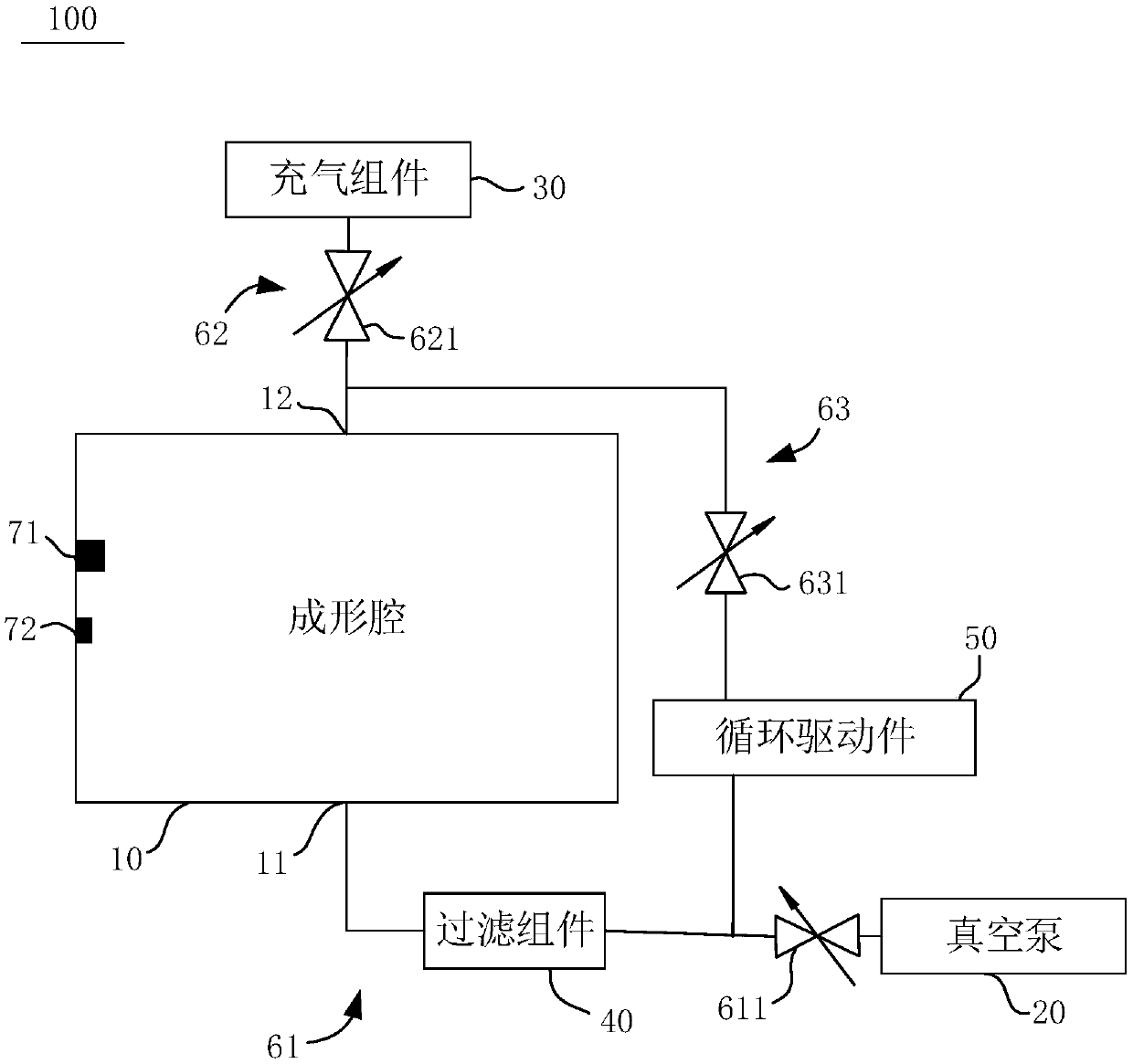
The embodiment of the invention provides an oxygen control method used for regulating and controlling the oxygen content in a forming cavity of a 3D printing system. The oxygen control method comprises the following steps that gas in the forming cavity starts to be pumped out; whether the gas pressure value in the forming cavity is lower than a preset gas pressure value or not is detected, and ifthe gas pressure value in the forming cavity is lower than the preset gas pressure value, protective gas starts to be injected into the forming cavity; whether the oxygen content in the forming cavityis lower than a preset oxygen content value or not is detected, and if the oxygen content is lower than the preset oxygen content value, pumping out of the gas in the forming cavity is stopped; and whether the gas pressure value in the forming cavity is higher than the standard external atmospheric pressure or not is detected, and if the gas pressure value in the forming cavity is higher than thestandard external atmospheric pressure, injecting of the protective gas into the forming cavity is stopped. According to the oxygen control method, the oxygen content in the forming cavity is rapidlylower than the preset oxygen content value, the laser 3D printing requirement is met, the regulating and controlling time is short, and the working efficiency is high. Meanwhile, the embodiment of the invention further provides an oxygen control device and the laser 3D printing system.

Description

Technical field [0001] The embodiment of the present invention belongs to the field of laser additive manufacturing. Specifically, it relates to an oxygen control method for adjusting the oxygen content inside a forming cavity to adapt to laser 3D printing. Meanwhile, the embodiment of the present invention also relates to an oxygen control device using the oxygen control method and a laser 3D printing system including the oxygen control device. Background technique [0002] Laser 3D printing is also called additive manufacturing. Existing additive manufacturing equipment widely adopts selective laser melting technology (Selective Laser Melting, SLM). SLM is an additive manufacturing technology for the direct forming of metal parts. This technology is based on the 3D data model and uses laser focus to focus the forming material In the incremental manufacturing method of layer-by-layer cladding and accumulation, the temperature in the forming cavity, the oxygen concentration, and...

Claims


Application Information

Patent Timeline
Patent Type & Authority Applications(China)
IPC IPC(8): B22F3/105B33Y40/00B33Y50/02
CPCB33Y40/00B33Y50/02B22F2999/00B22F10/00B22F12/90B22F12/70B22F10/32B22F10/28B22F10/77B22F2201/10B22F2201/02Y02P10/25
Inventor 许建波刘鹏宇姚锡禹董银刘旭飞龙雨陈根余陈焱高云峰
Owner HANS LASER TECH IND GRP CO LTD
Learn More