Laser cutting machine feeding device and working method based on coordinate recognition

A laser cutting machine and coordinate recognition technology, which is applied in laser welding equipment, manufacturing tools, metal processing equipment, etc., can solve the problems affecting the transportation, cutting effect, pipe bending, sinking, etc., and achieve the goal of improving the degree of processing automation and production efficiency Effect

Active Publication Date: 2022-02-01
安徽同兴科技发展有限责任公司
View PDF15 Cites 2 Cited by
  • Summary
  • Abstract
  • Description
  • Claims
  • Application Information

AI Technical Summary

Problems solved by technology

[0002] When the laser cutting machine feeds and transports the long pipe, it needs to slowly transport the processed surface of the long pipe to the bottom of the laser emitter. During the processing and transportation of the long pipe, due to its heavy weight, the middle part of the fixed pipe will bend , subsidence phenomenon, affecting the conveying and cutting effect

Method used


Image

  • Laser cutting machine feeding device and working method based on coordinate recognition
  • Laser cutting machine feeding device and working method based on coordinate recognition
  • Laser cutting machine feeding device and working method based on coordinate recognition

Examples


Embodiment Construction

[0017] In order to make the purpose, technical solutions and advantages of the embodiments of the present invention clearer, the technical solutions in the embodiments of the present invention will be clearly and completely described below in conjunction with the drawings in the embodiments of the present invention. Obviously, the described embodiments It is a part of embodiments of the present invention, but not all embodiments. Based on the embodiments of the present invention, all other embodiments obtained by persons of ordinary skill in the art without creative efforts fall within the protection scope of the present invention.

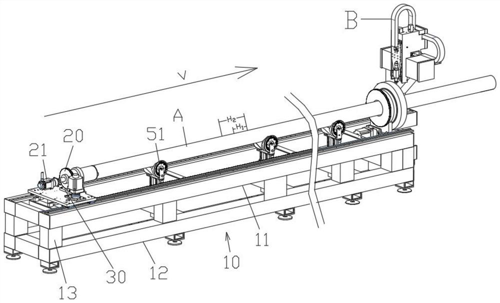
[0018] see Figure 1-3 As shown, a laser cutting machine feeding device based on coordinate recognition includes a conveying workbench 10 and a chuck assembly 20 that clamps a pipe A and slides along the conveying workbench 10 to the laser generator B. Inside the conveying workbench 10 The cavity is provided with a servo motor 21 that drives the ...


PUM


Abstract

The invention relates to the field of laser cutting machine equipment, and discloses a laser cutting machine feeding device based on coordinate recognition and its working method, including a conveying workbench, a chuck assembly, a servo motor, a base, and the inner cavity of the conveying workbench along the conveying direction A number of supporting frames are arranged at intervals, and the supporting frame includes first and second beams arranged in high and low positions. A lifting assembly is arranged between the first and second beams. The lifting assembly includes reducing wheels for supporting pipes and driving variable The diameter wheel reciprocates along the vertical direction of the cylinder, and the top of the conveying table is correspondingly provided with a middle hole for the variable diameter wheel to shuttle through. The inner cavity of the conveying table is also equipped with a controller electrically connected to the servo motor and the cylinder. By setting variable diameter wheels controlled by multiple lifting components, it can support and load long pipes during processing, ensure the conveying and cutting effects during processing, and realize automatic control.

Description

technical field [0001] The invention relates to the field of laser cutting machine equipment, in particular to a coordinate recognition-based laser cutting machine feeding device and a working method thereof. Background technique [0002] When the laser cutting machine feeds and transports the long pipe, it needs to slowly transport the processed surface of the long pipe to the bottom of the laser emitter. During the processing and transportation of the long pipe, due to its heavy weight, the middle part of the fixed pipe will bend , Subsidence phenomenon, affecting the conveying and cutting effect. Contents of the invention [0003] The invention aims at the deficiencies of the prior art, and provides a laser cutting machine feeding device based on coordinate recognition that can provide automatic feeding support during the long pipe processing process. [0004] The present invention solves the above-mentioned technical problems through the following technical means: a l...

Claims


Application Information

Patent Timeline
Patent Type & Authority Patents(China)
IPC IPC(8): B23K26/38B23K26/70
CPCB23K26/38B23K26/702
Inventor 罗群罗亮
Owner 安徽同兴科技发展有限责任公司
Why Eureka
Try Eureka