Weft accumulator sensing component and weft accumulator

A sensor component and weft feeder technology, which is applied in textiles, textiles, papermaking, looms, etc., can solve the problems of difficult adjustment of detection pressure, failure of Hall element detection, etc., to achieve constant yarn tension and prolong service life. , the effect of smooth operation

Pending Publication Date: 2020-01-21
徐建良
View PDF2 Cites 0 Cited by
  • Summary
  • Abstract
  • Description
  • Claims
  • Application Information

AI Technical Summary

Problems solved by technology

Among them, the magnetic steel is not only the triggering magnetic field that triggers the Hall element, but also acts as a part of generating the detection pressure. It is difficult to adjust the

Method used


Image

  • Weft accumulator sensing component and weft accumulator
  • Weft accumulator sensing component and weft accumulator
  • Weft accumulator sensing component and weft accumulator

Examples


Embodiment 1

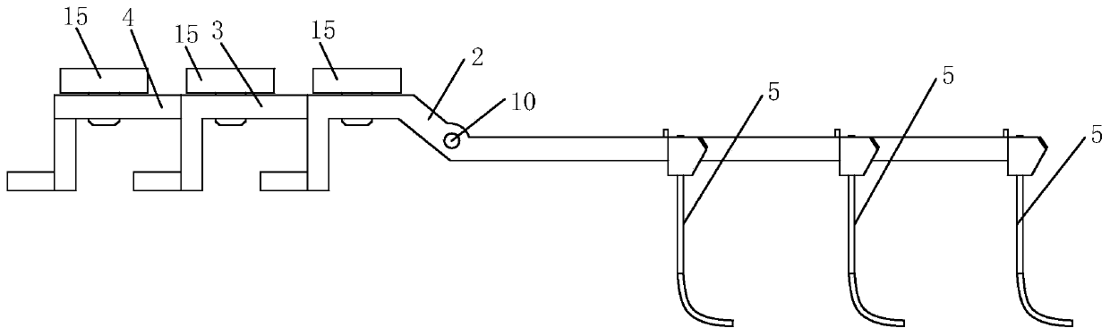
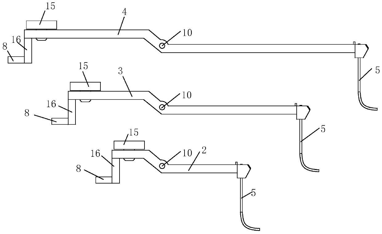
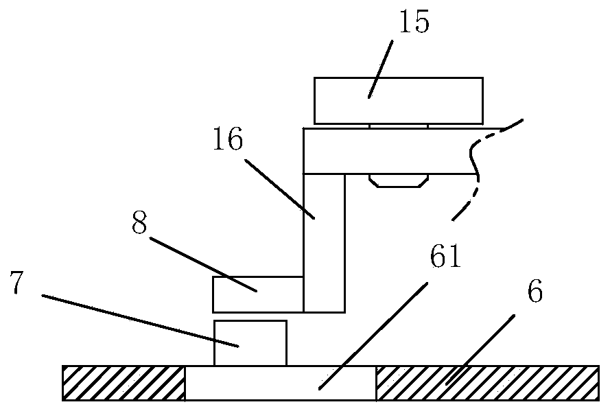
[0039] Example 1: Please refer to Figure 1-12 shown. A sensing component of a weft feeder in the present invention comprises a sensor seat 1, a short probe rod 2, a middle probe rod 3 and a long probe rod 4, a detection contact piece 5, and a motor control board 6, on which three groups of photoelectric The sensor 7 is provided with a mounting groove 11 on the upper side of the sensor seat 1, and the short probe rod 2, the middle probe rod 3 and the long probe rod 4 are placed side by side in the mounting groove 11, and the short probe rod 2, the middle probe rod 3 and the long probe rod 4 The middle part is hinged to the left side of the installation groove 11 through the revolving pin 7, and the middle part of the corresponding short probe rod 2, middle probe rod 3 and long probe rod 4 is provided with a through hole 10 for the revolving pin 7 to pass through, and the bottom of the mounting groove 11 The left side, the middle part and the right side are provided with a lef...

Embodiment 2

[0045] Example 2: Please refer to Figure 1-12 shown. A weft feeder using the sensor assembly of the weft feeder, comprising a motor protection case 20, a motor 30, a yarn winding disc 40, a yarn storage drum 50, and a shield 60, the motor 30 is arranged in the motor protection case 20, and the motor The right side of the protective case 20 is provided with a yarn winding disc 40 and a yarn storage drum 50 connected to the yarn winding disc 40. A shield 60 is connected from the upper side of the motor protection case 20 to the upper side of the yarn storage drum. It is characterized in that the sensor seat 1 is connected to Inside the shield 60, the motor control board 6 is connected to the side of the shield 60 close to the motor protection shell 20, the control end of the motor 30 is electrically connected to the motor control board 6, and the motor protection shell 20 is provided with an electrical connection with the motor control board 6. connection control button, the d...


PUM


Abstract

The invention discloses a weft accumulator sensing component and a weft accumulator. The weft accumulator sensing component comprises a sensor seat, a short probe, a medium probe, a long probe, detection contact plates and a motor control panel. The motor control panel is provided with three groups of photoelectric sensors, and the upper side of the sensor seat is provided with a mounting channel.The short probe, the medium probe and the long probe are arranged in parallel in the mounting channel; the middles of the short probe, the medium probe and the long probe are hinged to the left sideof the mounting channel through rotating pins; the left side, the middle and the right side of the bottom of the mounting channel are respectively provided with a left probe hole, a middle probe holeand a right probe hole; one ends of the right ends of the short probe, the medium probe and the long probe, which are located in the mounting channel, are respectively connected with the detection contact plates; the detection contact plates downwards correspondingly penetrates the left probe hole, the middle probe hole and the right probe hole respectively; the left ends of the probes are respectively provided with blocking plates, and the blocking plates are respectively correspondingly arranged above transmitters and receivers of the three groups of photoelectric sensors. The state is sensed by the detection contact plates at the right ends of the short probe, the medium probe and the long probe so as to control the opening, closing and rotating speed of a motor.

Description

technical field [0001] The invention belongs to the technical field of bags, and in particular relates to a sensor component of a weft feeder and a weft feeder. Background technique [0002] The fixed drum type weft feeder at home and abroad basically all adopts the technology similar to CN99200896.4 at present, and the number of parts is less, and the structure is also more compact. However, with the development of high-elastic fabrics on new circular knitting machines, the drum-type yarn feeder specially used for circular knitting machines can no longer meet the requirements, and a fixed drum-type weft feeder with higher performance must be used to adapt to the manufacture of high-elastic spandex yarns. . In addition, due to the increase in the weft insertion rate of economical rapier looms, it has become increasingly difficult for a large number of supporting drum-type weft feeders to meet the growing requirements. Many new economical rapier looms have to choose expensiv...

Claims


Application Information

Patent Timeline
IPC IPC(8): D03D51/00D03D47/34
CPCD03D47/34D03D51/00
Inventor 徐建良
Owner 徐建良
Why Eureka
Try Eureka