
Intelligent nondestructive testing device for spray welding of pipe row

A non-destructive testing and intelligent technology, applied in the direction of optical testing flaws/defects, etc., can solve the problems of affecting the testing process, cumbersome testing process, low efficiency, etc., and achieve the effect of improving testing accuracy, improving testing efficiency, and reasonable design.

Pending Publication Date: 2020-01-21
POURIN WELDING ENG
View PDF0 Cites 1 Cited by
  • Summary
  • Abstract
  • Description
  • Claims
  • Application Information

AI Technical Summary

Problems solved by technology

[0002] At present, the surfacing technology of boiler tube row has been well applied in practice. In the production of tube row, the tube row of each finished tube row needs to undergo non-destructive testing. The non-destructive testing is generally realized by manual operation, such as manual cleaning Dust, spraying water, etc., because the whole set of detection process is relatively cumbersome, so for the staff, the workload is relatively large, more importantly, it takes a long time, the efficiency is not high, and the manual operation creates The testing environment is relatively rough, which will increase the probability that the tube row will be affected by dirt during the testing process and affect the testing process

Method used


Image

  • Intelligent nondestructive testing device for spray welding of pipe row
  • Intelligent nondestructive testing device for spray welding of pipe row
  • Intelligent nondestructive testing device for spray welding of pipe row

Examples


Embodiment Construction

[0026] This part will describe the specific embodiment of the present invention in detail, and the preferred embodiment of the present invention is shown in the accompanying drawings. Each technical feature and overall technical solution of the invention, but it should not be understood as a limitation on the protection scope of the present invention.

[0027] In the description of the present invention, it should be understood that the orientation descriptions, such as up, down, front, back, left, right, etc. indicated orientations or positional relationships are based on the orientations or positional relationships shown in the drawings, and are only In order to facilitate the description of the present invention and simplify the description, it does not indicate or imply that the device or element referred to must have a specific orientation, be constructed and operated in a specific orientation, and thus should not be construed as limiting the present invention.

[0028] I...


PUM


Abstract

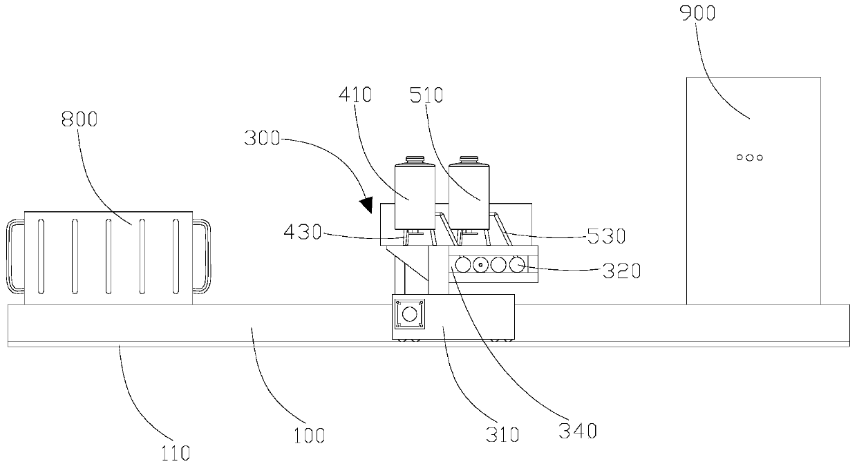
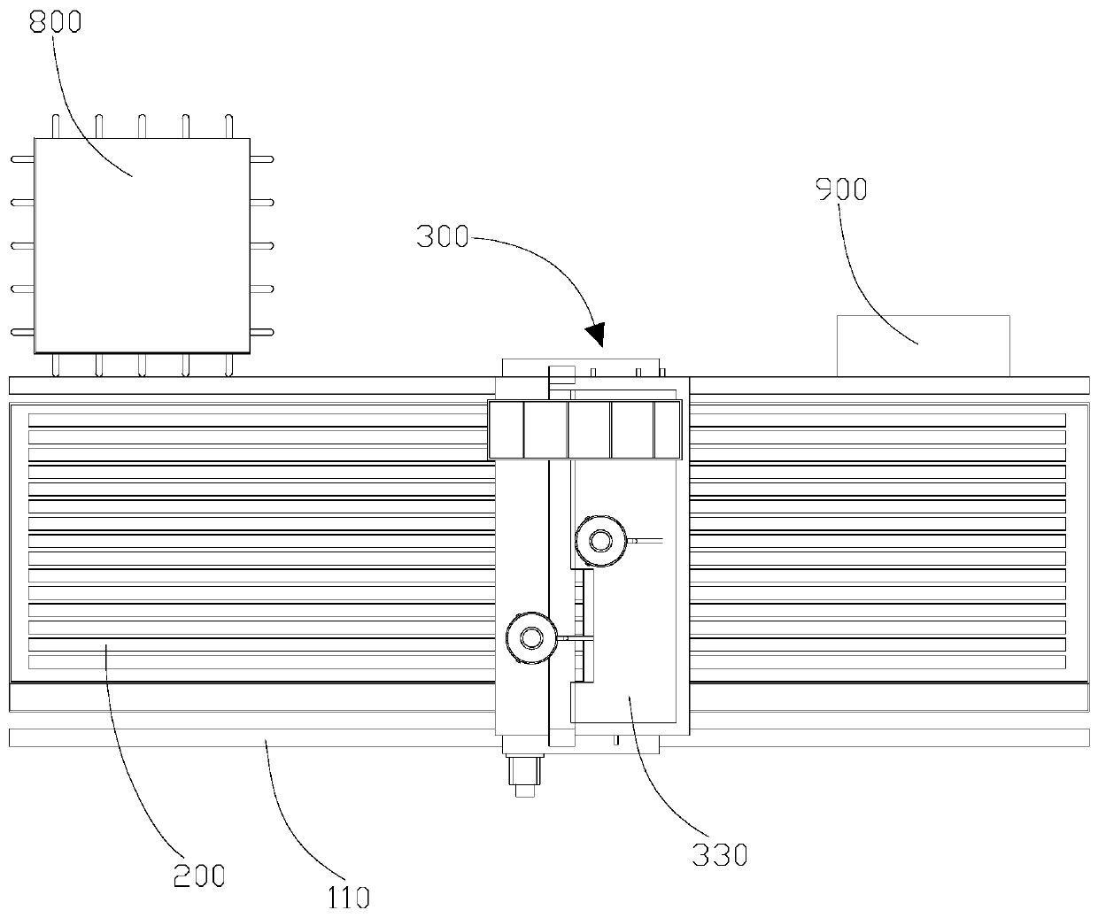
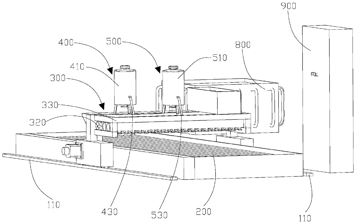
The invention discloses an intelligent nondestructive testing device for spray welding of a pipe row. The intelligent nondestructive testing device comprises a water storage tank, a trolley, a permeation mechanism, a developing mechanism, a first spray head and a second spray head, wherein the water storage tank is used for storing the pipe row to be detected; the trolley can do reciprocating motion relative to the water storage tank and is provided with a control mechanism and two movable sliding tables connected with the control mechanism; the two movable sliding tables are mounted on the outer walls of the two sides of the water storage tank correspondingly; the permeation mechanism is used for spraying a penetrant to the pipe row; the developing mechanism is used for spraying a developing agent to the pipe row; the first spray head is used for cleaning the pipe row; the second spray head is used for air-drying the pipe row; and the permeation mechanism, the developing mechanism, the first spray head and the second spray head are all arranged on the trolley and connected with the control mechanism. Compared with the traditional technology, the intelligent nondestructive testingdevice is reasonable in design, manual operation is not needed, intelligent automatic detection in the whole process can be achieved, a more optimized detection environment is created for the pipe row, the detection efficiency of the industrial pipe row is improved, and the detection precision of the industrial pipe row is also improved.

Description

technical field [0001] The invention relates to the field of processing of spray-welded pipe rows, in particular to intelligent non-destructive testing equipment for spray-welded pipe rows. Background technique [0002] At present, the surfacing technology of boiler tube row has been well applied in practice. In the production of tube row, the tube row of each finished tube row needs to undergo non-destructive testing. The non-destructive testing is generally realized by manual operation, such as manual cleaning Dust, spraying water, etc., because the whole set of detection process is relatively cumbersome, so for the staff, the workload is relatively large, more importantly, it takes a long time, the efficiency is not high, and the manual operation creates The testing environment is relatively rough, which will increase the probability that the tube row will be affected by dirt during the testing process and affect the testing process. Contents of the invention [0003] ...

Claims


Application Information

Patent Timeline
Patent Type & Authority Applications(China)
IPC IPC(8): G01N21/91
CPCG01N21/91
Inventor 陆卓冀梁穗江聂月莲
Owner POURIN WELDING ENG
Learn More