Rotating bed with concentric corrugated rings

A technology of corrugated rings and rotating beds, applied in chemical methods for reacting liquid and gaseous media, chemical/physical/physicochemical fixed reactors, chemical/physical/physicochemical processes, etc., capable of solving limitations, rotating beds To solve the problem of low mass transfer efficiency and achieve the effect of improving the circumferential distribution of liquid and improving the efficiency of gas-liquid mass transfer

Pending Publication Date: 2020-01-24
浙江华科化工设备有限公司
View PDF8 Cites 0 Cited by
  • Summary
  • Abstract
  • Description
  • Claims
  • Application Information

AI Technical Summary

Problems solved by technology

The rotating bed belongs to the plate rotor rotating bed, which has the advantages of simple structure and low manufact

Method used


Image

  • Rotating bed with concentric corrugated rings
  • Rotating bed with concentric corrugated rings
  • Rotating bed with concentric corrugated rings

Examples


Embodiment 1

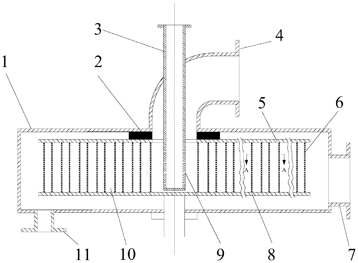
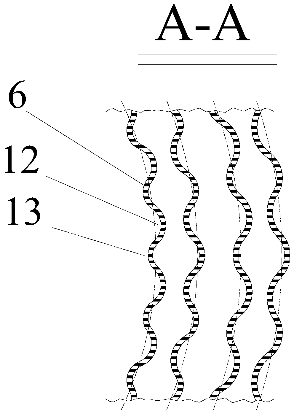
[0015] Embodiment 1: as attached figure 1 As shown, this concentric corrugated ring rotary bed mainly includes a cavity 1, a rotor 10 is arranged in the cavity 1, a dynamic seal 2 is arranged between the rotor 10 and the cavity 1, and a gas seal is arranged on the side of the cavity 1. The inlet pipe 7 is provided with a liquid outlet pipe 11 on the bottom plate of the cavity 1; the rotating shaft 21 of the rotor 11 penetrates from the bottom plate of the cavity 1, and the liquid inlet pipe 3 penetrates the cavity 1 and the rotor from the upper part of the cavity 1 In the central chamber 22 of 10, the liquid inlet pipe 3 with the upper opening and the bottom closed is installed coaxially with the rotating shaft 21, and several liquid outlet holes 9 are also opened on the pipe wall of the liquid inlet pipe 3; the gas outlet pipe 4 is arranged on the cavity The upper panel of the body 1 and communicates with the central chamber 22 of the rotor 10; the rotor 10 is composed of an ...

Embodiment 2

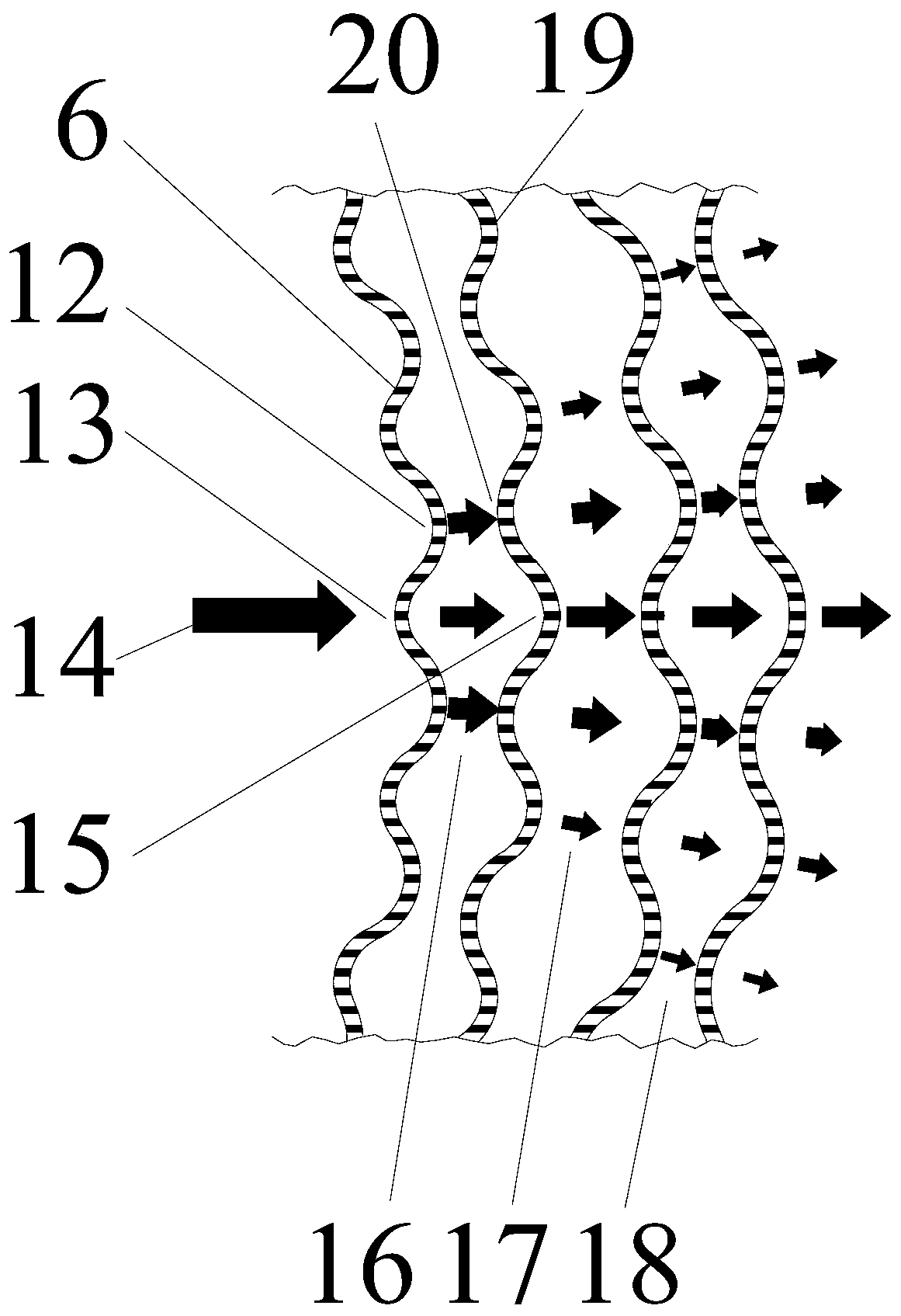
[0019] Embodiment 2: When the present invention is used for rectification, the gas from the reboiler enters the inner cavity of the cavity 1 from the gas inlet pipe 7, passes through the rotor 10 in the radial direction, contacts with the liquid in countercurrent, and finally passes through the gas outlet The pipe 4 enters the condenser to condense to obtain the rectification product; part of the condensate enters from the liquid inlet pipe 3 as reflux liquid, enters the interior of the rotor 10 through the liquid outlet hole 9 on the liquid inlet pipe, and is accelerated and thrown out under the action of centrifugal force. The liquid is crushed into fine liquid foam and liquid silk, and contacts with the gas countercurrently for mass transfer and heat transfer. The liquid enters the reboiler through the liquid outlet pipe 11 to be heated, and the rectified product is discharged from the reboiler.

[0020] With ethanol-water as the substance system, under the rotating speed of...


PUM


Abstract

The invention discloses a rotating bed with concentric corrugated rings, and relates to the field of gas-liquid mass transfer equipment. The rotating bed with the concentric corrugated rings mainly comprises a cavity, wherein a rotor is arranged in the cavity, a rotating shaft of the rotor penetrates through a baseboard of the cavity, a liquid inlet pipe penetrates through the cavity and a centralchamber of the rotor from the upper portion of the cavity, the liquid inlet pipe and the rotating shaft are installed coaxially, and a plurality of liquid outlet holes are formed in a pipe wall of the liquid inlet pipe; a gas outlet pipe is arranged on an upper panel of the cavity, and communicates with the central chamber of the rotor; and the rotor is composed of an upper disc and a lower disc,one set of concentric corrugated rings with the diameters evenly increasing are fixed between the upper disc and the lower disc, the concentric corrugated rings are composed of multiple peaks and troughs, and any two of the concentric corrugated rings are distributed in a staggered mode, so that the peaks of each concentric corrugated ring face the corresponding troughs of the corresponding adjacent concentric corrugated rings. The rotating bed with the concentric corrugated rings has the advantages that the rotor of the rotating bed is a rotor with the concentric corrugated rings, and circumferential distribution of liquid can be greatly improved, so that the gas-liquid mass transfer efficiency of the rotating bed is improved.

Description

technical field [0001] The invention relates to the field of gas-liquid mass transfer equipment, in particular to a rotary bed with concentric corrugated rings. Background technique [0002] As a new type of process intensification equipment, the high-gravity rotating bed can greatly reduce the volume of the equipment, thereby improving production efficiency and reducing costs. It has been successfully applied in many chemical fields such as rectification, absorption and reaction. The principle of the high-gravity rotating bed is to generate a centrifugal force field by rotating the rotor, and use the centrifugal force field to replace the gravity field. Under the high-gravity field, the liquid is torn into micron-sized droplets, liquid foam and liquid film, which greatly strengthens the multi- Mass transfer and heat transfer process between phase flows Gas-liquid mass transfer process. Compared with traditional plate towers and packed towers, the gas-liquid mass transfer r...

Claims


Application Information

Patent Timeline
IPC IPC(8): B01J19/18B01J10/00
CPCB01J19/1806B01J10/00B01J19/0066
Inventor 李育敏姜建平汪峰陈加齐姜孝静刘国林
Owner 浙江华科化工设备有限公司
Why Eureka
Try Eureka