Method for machining end surfaces of inner cavity holes by using two-end cutter

A technology of hole end face and tool, which is applied in the field of workpiece processing, can solve the problems of difficult control of size, tool chipping and damage, low efficiency of single-edged knives, etc., and achieve the effect of easy control of processing size, reduction of tool cost, and not easy to let the knife phenomenon

Pending Publication Date: 2020-01-24
SHANDONG UNIV
View PDF9 Cites 1 Cited by
  • Summary
  • Abstract
  • Description
  • Claims
  • Application Information

AI Technical Summary

Problems solved by technology

[0004] (1) Low processing efficiency: Due to the different tools for processing the upper and lower end faces, tool replacement is required, which increases the idle travel time and tool change time, and the processing efficiency is low. In mass production, the low efficiency of single-edged knife scraping is prominent;
[0005] (2) The upper and lower end faces are not perpendicular to the axis of the hole: due to the limitation of the aperture, the tool bar cannot be too thick, and the rigidity of the tool bar is poor; the cutting edge is in full contact with the machined end face during processing, and the cutting force is large, causing the tool body and the tool bar to bend and deform, resulting in The processed end face is not perpendicular to the hole axis; in the case of high verticality requirements of the workpiece, an additional process is required for correction, and the processing efficiency is low
[0006] (3) The upper and lower end faces are not parallel, and the size is difficult to control: when machining the upper and lower end faces, the direction of the tool is different, resulting in inconsistent bending directions of the tool bar, and the processed upper and lower end faces are not parallel; and the processed end faces have convex or concave centers, which is difficult to control Dimensions between the upper and lower end faces; when the requirements for parallelism and dimensional accuracy of the upper and lower end faces of the workpiece are high, an additional process is required for correction, and the processing efficiency is low
[0007] (4) The roughness of the end surface is not easy to control: due to the poor rigidity of the tool holder and the large cutting force, tool vibration is prone to occur during the processing, which affects the surface quality; low efficiency
[0008] (5) The tool life is short and the cost is high: due to the poor rigidity of the tool bar and the large cutting force, the tool vibration is caused during the processing, which is easy to cause tool chipping and damage. In mass production, the tool needs to be replaced midway, and the efficiency is low.
Moreover, two tools are required to process the upper and lower end faces, and the tool cost is relatively high

Method used


Image

  • Method for machining end surfaces of inner cavity holes by using two-end cutter
  • Method for machining end surfaces of inner cavity holes by using two-end cutter
  • Method for machining end surfaces of inner cavity holes by using two-end cutter

Examples


Embodiment 1

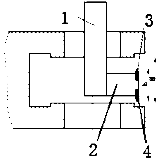
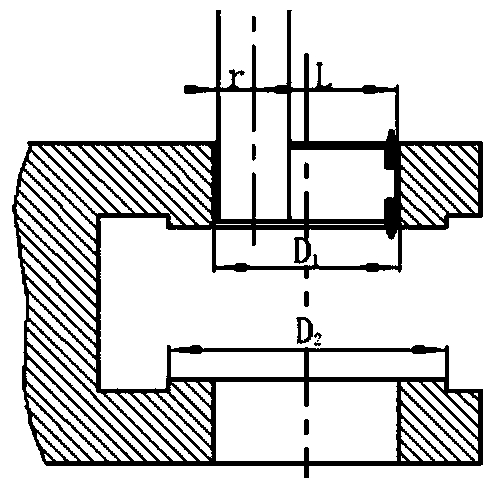
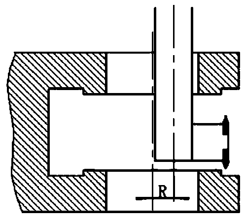
[0046] Attached below Figure 1-Figure 5 The present invention is described in detail, specifically, the structure is as follows:

[0047] This embodiment provides a method of using a double-ended tool to process the end face of the inner cavity hole. The same double-ended tool is used to process the upper end surface and the lower end surface of the inner cavity hole of the workpiece, including the tool holder 1, the tool body 2, the upper tool head 3 and the lower tool. Head 4, the cutter body is installed on one side of the cutter bar, the upper and lower ends of the front end of the cutter body are respectively installed with the upper cutter head 3 and the lower cutter head 4, and the tip of the upper cutter head 3 faces upwards, and the tip of the lower cutter head 4 faces upwards. Down. The distance h between the tip of the upper cutter head 3 and the lower cutter head 4 is smaller than the distance H between the upper and lower end surfaces.

[0048] Taking the lower...


PUM


Abstract

The invention discloses a method for machining end surfaces of inner cavity holes by using a two-end cutter, and solves the problems of low precision, low machining efficiency and short life of the cutter in traditional end surface machining; and the cutter has no need to be changed during machining of upper and lower end surfaces of the inner cavity holes, so that the machining efficiency is high. The method is characterized in that the lower end surfaces / the upper end surfaces of the inner cavity holes are firstly machined; the two-end cutter is clamped on a main shaft; the main shaft is oriented to stop the two-end cutter above the centers of the holes, and then, is deviated from the centers of the holes by a set distance to feed the two-end cutter from upper end holes to a molding cavity; after the two-end cutter enters inner cavities, the main shaft is leveled with the centers of the holes, and then, the center of a cutter rod moves to deviate from the centers of the holes by a set distance R; the main shaft is started, and a machine tool drives the main shaft to perform a circular interpolation motion with the centers of the holes as circle centers and with R as radius; aftermachining of the lower end surfaces / the upper end surfaces, the two-end cutter machines the lower end surfaces / the upper end surfaces according to a given feeding quantity; and after machining, the two-end cutter is deviated from the machined end surfaces by a set distance, the center of the two-end cutter is aligned to the centers of the holes, and the cutter is withdrawn.

Description

technical field [0001] The invention relates to the field of workpiece processing, in particular to a method for processing the end face of an inner cavity hole by using a double-head tool. Background technique [0002] In the processing of shell parts and planetary gear brackets, there are usually processing requirements for the end faces of the inner cavity, such as: the upper and lower end faces are parallel and perpendicular to the hole axis; ensure the size requirements between the upper and lower end faces; the upper and lower end faces meet flatness and roughness Require. Due to the narrow and closed inner cavity space, the tool can only enter and exit through the inner cavity hole, which greatly restricts the choice of processing methods. At present, the method of scraping the inner end surface with a single-edged knife of an ordinary boring machine is usually used for the inner cavity hole, but this method is not only difficult to operate, but also has low efficien...

Claims


Application Information

Patent Timeline
Patent Type & Authority Applications(China)
IPC IPC(8): B23C3/12
CPCB23C3/124
Inventor 刘增文张艺琳王再海张丽孙悦
Owner SHANDONG UNIV
Why Eureka
Try Eureka