
Gear milling machine tool

A technology for milling gears and machine tools, which is applied in the direction of gear teeth manufacturing devices, gear cutting machines, belts/chains/gears, etc. It can solve the problems of increasing difficulty, hob axial runout, and not wide, so that it is not easy to move relative to each other and avoid left and right Offset, stability-enhancing effects

Inactive Publication Date: 2020-01-24
蔡玉明
View PDF4 Cites 0 Cited by
  • Summary
  • Abstract
  • Description
  • Claims
  • Application Information

AI Technical Summary

Problems solved by technology

[0002] Gears are an important part of modern mechanical transmission. From national defense machinery to civil machinery, from heavy industrial machinery to light industrial machinery, gear transmission is widely used. Helical gears are a kind of gears. In the manufacturing process of helical gears, gear hobbing machines When machining helical gears, it is difficult to determine the direction of additional motion. In addition, the change of factors such as milling method, workpiece spiral direction and hob spiral direction increases the difficulty of judgment, and the hob is also prone to shafting during processing. To jump, further increasing the difficulty of additional motion judgment

Method used


Image

  • Gear milling machine tool
  • Gear milling machine tool
  • Gear milling machine tool

Examples


Embodiment

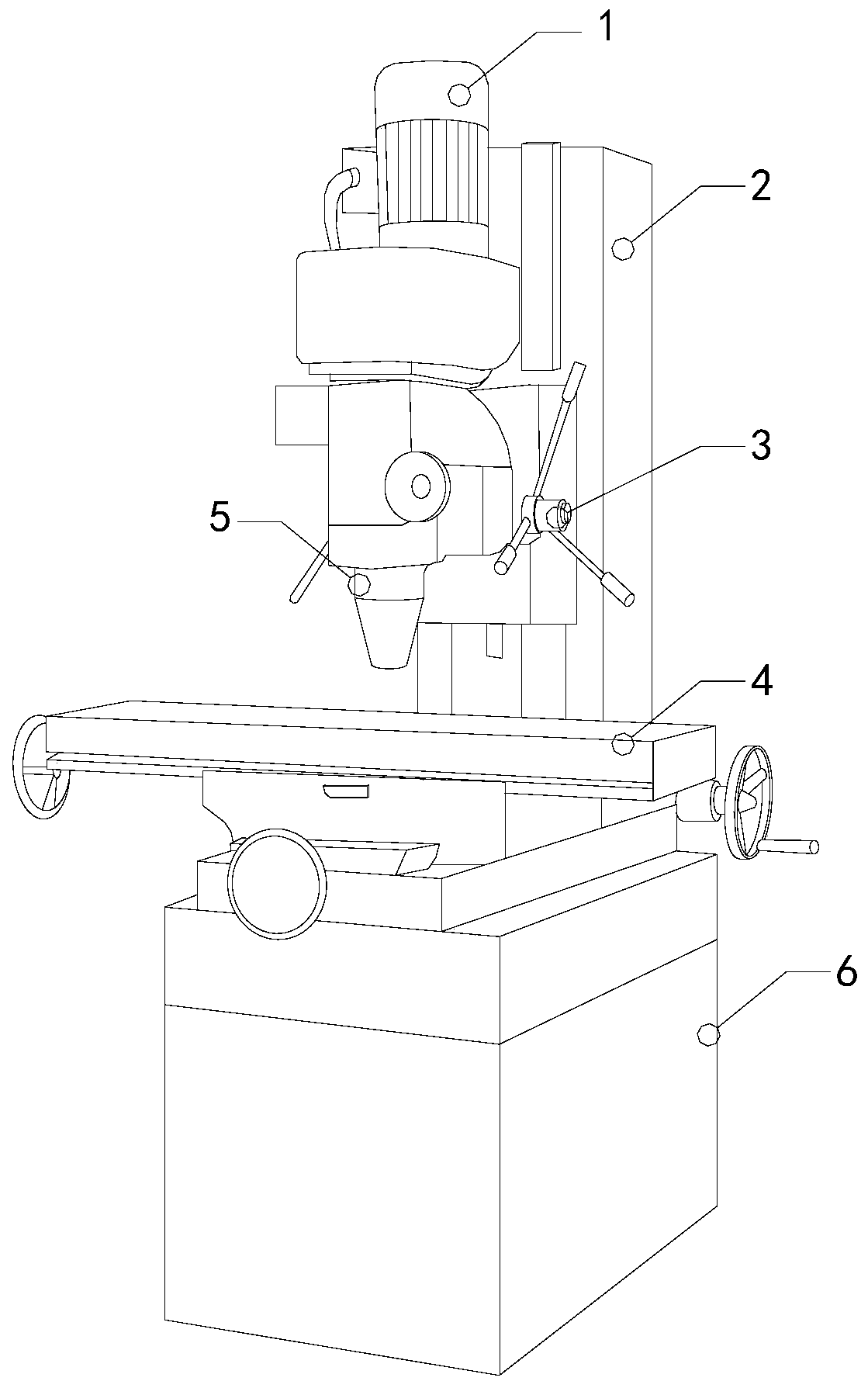
[0028] see Figure 1-Figure 6 , the present invention provides a gear milling machine tool, the structure of which includes a motor 1, an electric control box 2, a control hand 3, a mobile lathe 4, a cutter head structure 5, and a bottom box 6, and a mobile Lathe 4, an electric control box 2 is vertically welded on the bottom box 6 next to the mobile lathe 4, a cutter head structure 5 is arranged directly above the mobile lathe 4, and the cutter head structure 5 is mechanically connected to the output shaft of the motor 1, The motor 1 is close to the top of the electric control box 2 and is electrically connected with it.

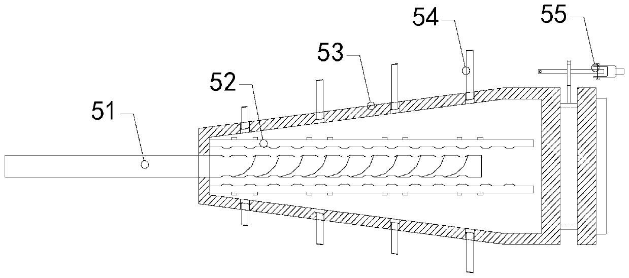
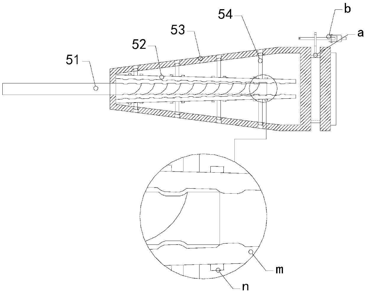
[0029] Described cutter head structure 5 comprises cutter head 51, clamp bar 52, shell 53, locking bar 54 and forms, and described shell 53 is the hollow taper structure, not only can clamp cutter head 51, also allows clamp bar 52 to possess sufficient space, the end of the housing 53 with a relatively small diameter clamps the cutter head 51, the cutter h...


PUM


Abstract

The invention discloses a gear milling machine tool. The gear milling machine tool structurally includes a motor, an electric control box, a control hand, a mobile lathe, a cutter head structure and abottom box. The mobile lathe is installed on the top end surface of the bottom box, the electric control box is vertically welded to the bottom box next to the mobile lathe, and the cutter head structure is arranged directly above the mobile lathe. The cutter head structure is mechanically connected with an output shaft of the motor. The motor is closely attached to the top end of the electric control box and is electrically connected with the electric control box. The cutter head structure includes a cutter head, a clamping rod, a shell and a locking rod. The cutter head is locked from the inside through the cooperation of the locking rod, a benchmark structure and other structures and prevented from generating axial jump. In addition, the motor is used for driving a pushing machine to rotate synchronously to push the direction of the front and rear movement of a mark floating machine to determine the direction of the additional movement of a helical gear, and the operation is simpleand clear.

Description

technical field [0001] The invention relates to the field of gear manufacturing, in particular to a gear milling machine tool. Background technique [0002] Gears are an important part of modern mechanical transmission. From national defense machinery to civil machinery, from heavy industrial machinery to light industrial machinery, gear transmission is widely used. Helical gears are a kind of gears. In the manufacturing process of helical gears, gear hobbing machines When machining helical gears, it is difficult to determine the direction of additional motion. In addition, the change of factors such as milling method, workpiece spiral direction and hob spiral direction increases the difficulty of judgment, and the hob is also prone to shafting during processing. Jumping to the direction further increases the difficulty of additional motion judgment. Contents of the invention [0003] Aiming at the deficiencies of the prior art, the present invention is realized through t...

Claims


Application Information

Patent Timeline
IPC IPC(8): B23F5/20B23F23/12B23F23/00
CPCB23F5/20B23F23/00B23F23/1243
Inventor 蔡玉明
Owner 蔡玉明
Learn More