

Plasma welding robot
A plasma welding and robot technology, applied in plasma welding equipment, welding equipment, metal processing equipment, etc., can solve the problems of complicated welding, difficult welding quality control, low welding production efficiency, etc., and achieve the effect of increasing the rotation angle
- Summary
- Abstract
- Description
- Claims
- Application Information
AI Technical Summary
Problems solved by technology
Method used
Image

Examples
Embodiment
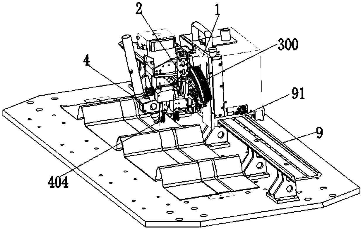
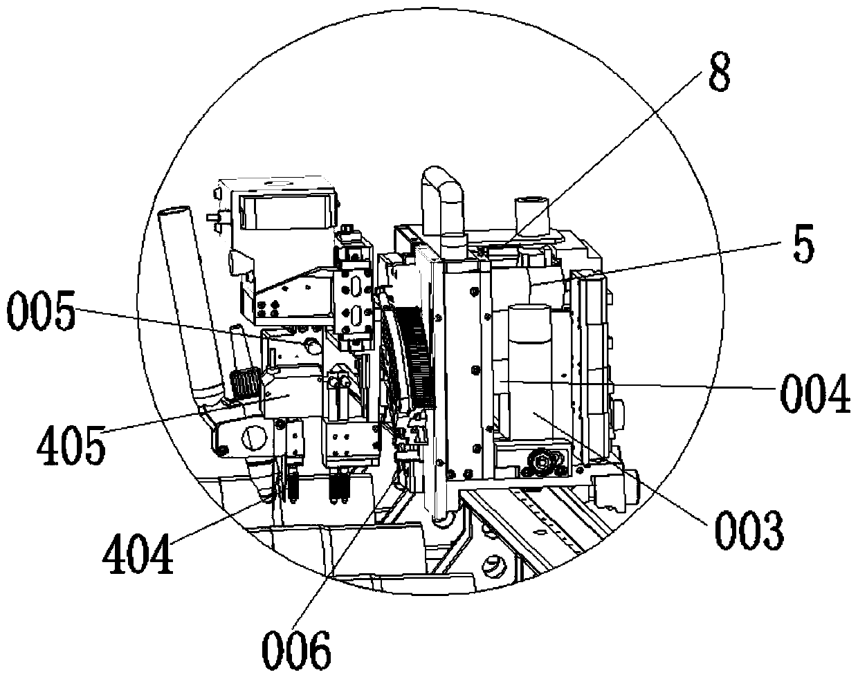
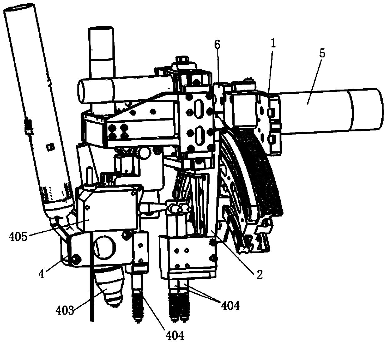
[0025] A plasma welding robot such as Figure 1-Figure 8As shown, it includes a track 9 and a welding trolley 91. The welding trolley 91 is provided with a driving traveling mechanism and its support 1, a welding torch angle adjustment mechanism, a welding torch position adjustment mechanism 402 and its support 2 of the welding torch. The driving traveling mechanism support 1 is provided with R-axis motor R-axis motor 004, the welding torch angle adjustment mechanism 300 is arranged between the welding torch position adjustment mechanism support 2 and the driving travel mechanism support 1, the welding torch 4 realizes the adjustment of the angle through the welding torch angle adjustment mechanism; the welding torch position adjustment mechanism 402 is provided with a welding torch Bracket 406, welding torch 4 is positioned on welding torch bracket 406; The welding torch position adjustment mechanism is provided with a position adjustment R-axis motor, which realizes the posit...
PUM
 Abstract
Description
Claims
Application Information