Cutter state monitoring system based on electromagnetic induction and radio frequency identification technology

A radio frequency identification technology and state monitoring system technology, applied in manufacturing tools, measuring/indicating equipment, metal processing equipment, etc., to achieve the effect of distance optimization and real-time stable transmission

Inactive Publication Date: 2020-01-24
HUAZHONG UNIV OF SCI & TECH
View PDF8 Cites 4 Cited by
  • Summary
  • Abstract
  • Description
  • Claims
  • Application Information

AI Technical Summary

Problems solved by technology

[0005] Aiming at the above defects or improvement needs of the prior art, the present invention provides a tool condition monitoring system based on electromagnetic induction and radio frequency identification technology, wherein the power supply circuit board, the energy transmission coil and the power supply end radio frequency identification coil are fixed on the machine tool spindle On the tool handle, the energy receiving coil, the sensing circuit board and the radio frequency identification coil at the sensing end are fixed on the tool handle, which can not only provide a stable power supply for the sensing device when the tool rotates at high speed, but also continue to supply power after the tool stops working , to avoid the problem of low work efficiency caused by frequent battery replacement, and at the same time, it can realize low power consumption and high stability data transmission function, so it is especially suitable for the application of tool status monitoring

Method used


Image

  • Cutter state monitoring system based on electromagnetic induction and radio frequency identification technology
  • Cutter state monitoring system based on electromagnetic induction and radio frequency identification technology
  • Cutter state monitoring system based on electromagnetic induction and radio frequency identification technology

Examples


Embodiment Construction

[0030] In order to make the objectives, technical solutions and advantages of the present invention clearer, the following further describes the present invention in detail with reference to the accompanying drawings and embodiments. It should be understood that the specific embodiments described herein are only used to explain the present invention, but not to limit the present invention. In addition, the technical features involved in the various embodiments of the present invention described below can be combined with each other as long as they do not conflict with each other.

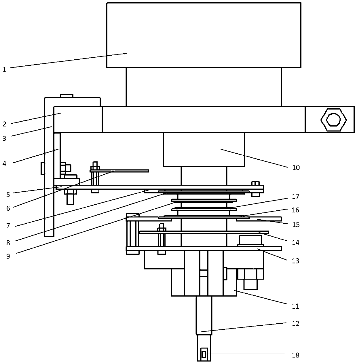
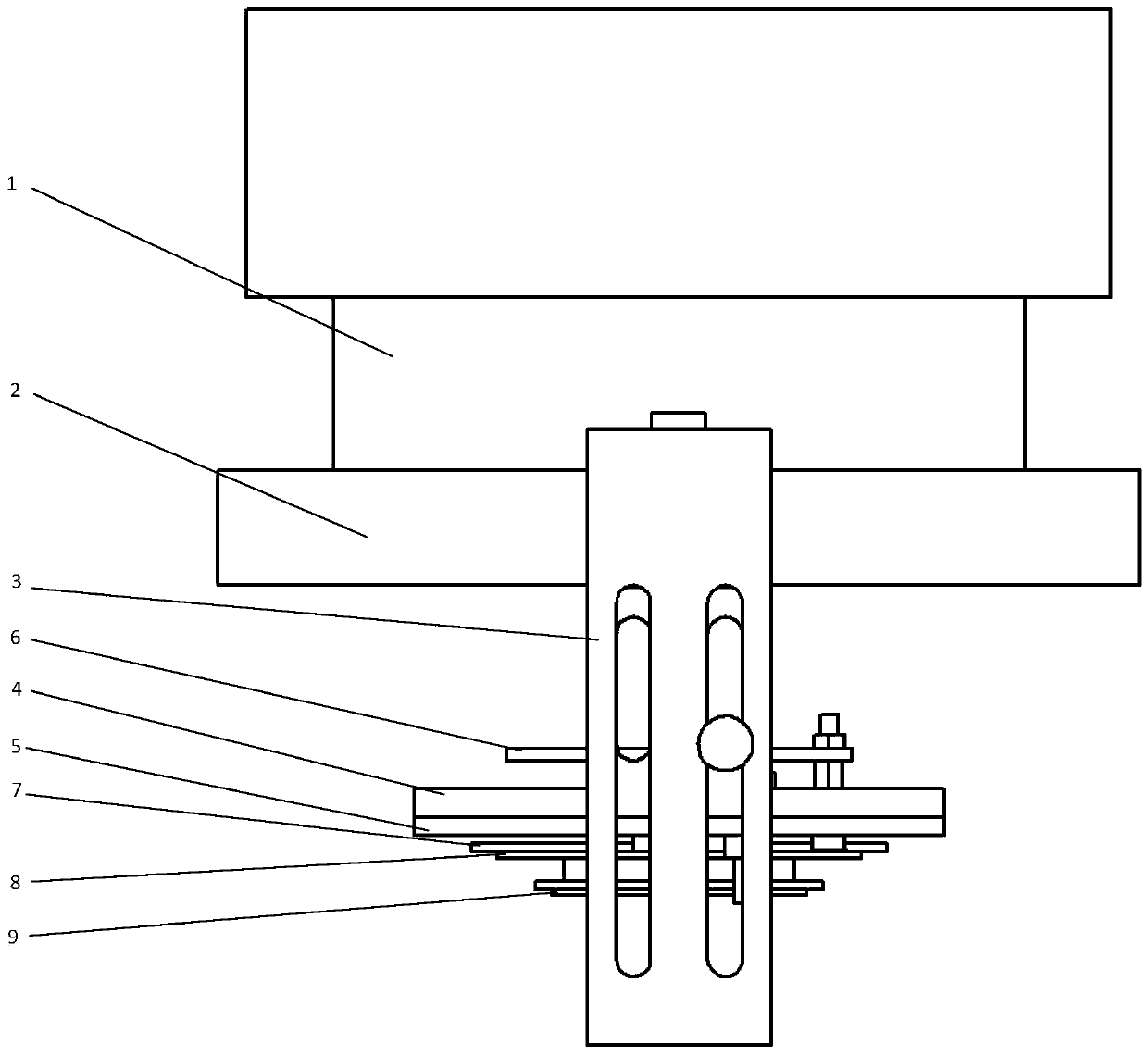
[0031] Such as figure 1 As shown, the embodiment of the present invention provides a tool condition monitoring system based on electromagnetic induction and radio frequency identification technology. The system includes a connection device, a power supply device, a sensing device 18 and a data transmission device. Among them:

[0032] The connecting device includes a spindle clamping base 2, a tool holde...


PUM


Abstract

The invention belongs to the field of cutter state monitoring and specifically discloses a cutter state monitoring system based on electromagnetic induction and a radio frequency identification technology. The system comprises a connecting device, a power supply device, an induction device and a data transmission device, wherein the connecting device is used for fixation; the power supply device comprises a power supply circuit board fixed on a machine tool main shaft, an energy sending coil as well as an energy receiving coil and an induction circuit board fixed on a cutter handle, and the power supply device is used for wireless transmission of electric energy under electromagnetic induction effects; the induction device is used for monitoring cutter states; and the data transmission device comprises a radio frequency identification coil on a power supply end and a radio frequency identification coil on an induction end, and the data transmission device is used for wireless communication in a radio frequency identification mode. The system disclosed by the invention has the beneficial effects that acquisition of continuous and stable electric energy by the induction device and the data transmission device can be ensured; a lithium battery does not need to be replaced frequently; a stable data transmission circuit can be formed; and real-time and stable transmission of data collected by the induction device can be guaranteed.

Description

Technical field [0001] The invention belongs to the field of tool condition monitoring, and more specifically, relates to a tool condition monitoring system based on electromagnetic induction and radio frequency identification technology. Background technique [0002] Intelligent perception of processing conditions is an important part of intelligent manufacturing. It provides reliable data for optimizing cutting parameters and judging tool status. It is of great significance for the aerospace manufacturing industry to achieve high-quality manufacturing of difficult-to-machine materials and complex thin-walled parts. In the current machining process, the tool physical quantity monitoring methods mainly include ex-situ sensing and wired transmission of electric energy and wired transmission signal mode, in-situ sensing and wired transmission of electric energy and wired transmission signal method, in-situ sensing and lithium battery transmission of electric energy and wireless Tra...

Claims


Application Information

Patent Timeline
Patent Type & Authority Applications(China)
IPC IPC(8): B23Q17/09
CPCB23Q17/09
Inventor 张小明项瑞昌刘玉婵夏峥嵘陶建民杨滨涛施达明黄涛张东马森林丁汉
Owner HUAZHONG UNIV OF SCI & TECH
Why Eureka
Try Eureka