Cutting device for large-diameter plastic blow-down pipes

A technology for plastic pipes and cutting devices, applied in metal processing and other directions, can solve the problems of low processing safety, inability to adjust the feed depth, and inflexible pipe processing, so as to achieve improved safety, flexible cutting effect, and stable lowering of the knife. Effect

Inactive Publication Date: 2020-01-24
太仓久庄管业有限公司
View PDF0 Cites 5 Cited by
  • Summary
  • Abstract
  • Description
  • Claims
  • Application Information

AI Technical Summary

Problems solved by technology

[0003] In the process of processing sewage pipes, it is necessary to cut them according to the length of use. The existing cutting devices have shortcomings in use. Most of the large-diameter pipes are cut by machinery, but manual rotation of the cutting device is still required during the cutting process, and the processing safety is low. , before the cutting can be completed. Secondly, the depth of the existing device cannot be adjusted, and it is not flexible enough to process pipes of different thicknesses.

Method used


Image

  • Cutting device for large-diameter plastic blow-down pipes
  • Cutting device for large-diameter plastic blow-down pipes
  • Cutting device for large-diameter plastic blow-down pipes

Examples


Embodiment 1

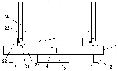
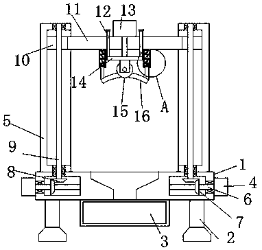
[0023] refer to Figure 1-3 , a large-diameter sewage plastic pipe cutting device, including a base 1, the two ends of the side of the base 1 are provided with cavities, the side of the base 1 is installed with a first motor 4, and the output shaft of the first motor 4 is inserted into the cavity. And connected with a rotating shaft 6, a first bevel gear 7 is fixedly sleeved on the rotating shaft 6, a support column 5 is fixed on both sides of the top of the base 1, a chute is opened on the side of the support column 5, and the inner part of the chute is rotated and connected with a wire Rod 9, the screw rod 9 penetrates the support column 5 and is inserted into the cavity, the bottom end of the screw rod 9 is fixedly sleeved with a second bevel gear 8, the first bevel gear 7 is meshed with the second bevel gear 8 for transmission, and the screw rod 9 is on the The sliding block 10 is sleeved through a thread, a supporting plate 11 is fixed between the two sliding blocks 10, a...

Embodiment 2

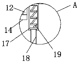
[0028] refer to figure 1 , Figure 4-5 , a large-diameter sewage plastic pipe cutting device, including a base 1, the two ends of the side of the base 1 are provided with cavities, the side of the base 1 is installed with a first motor 4, and the output shaft of the first motor 4 is inserted into the cavity. And connected with a rotating shaft 6, a first bevel gear 7 is fixedly sleeved on the rotating shaft 6, a support column 5 is fixed on both sides of the top of the base 1, a chute is opened on the side of the support column 5, and the inner part of the chute is rotated and connected with a wire Rod 9, the screw rod 9 penetrates the support column 5 and is inserted into the cavity, the bottom end of the screw rod 9 is fixedly sleeved with a second bevel gear 8, the first bevel gear 7 is meshed with the second bevel gear 8 for transmission, and the screw rod 9 is on the The sliding block 10 is sleeved through a thread, a supporting plate 11 is fixed between the two sliding ...


PUM


Abstract

The invention discloses a cutting device for large-diameter plastic blow-down pipes. The cutting device comprises a base. Cavities are formed in the two ends of the side face of the base. A first motor is installed on the side face of the base. An output shaft of the motor is inserted into the cavities and is connected with rotary shafts. The rotary shafts are fixedly sleeved with first bevel gears. Supporting columns are fixed to the two sides of the top of the base. Sliding grooves are formed in the side faces of the supporting columns. Lead screws are rotatably connected into the sliding grooves and penetrate through the supporting columns to be inserted into the cavities. The bottom ends of the lead screws are fixedly sleeved with second bevel gears. According to the cutting device forthe large-diameter plastic blow-down pipes, second motors and racks are arranged so that the blow-down pipes can be evenly rotated during cutting, the rotating stability is high, and the machining safety is improved; and meanwhile, through the arrangement of the first motor, the lead screws and a supporting plate, the cutting depth can be adjusted conveniently, blow-down pipes with different thicknesses can be cut conveniently, using is convenient, and the cutting effect is flexible.

Description

technical field [0001] The invention relates to the technical field of pipe processing, in particular to a large-diameter sewage-discharging plastic pipe cutting device. Background technique [0002] Plastic pipes are high-tech composite chemical building materials, and chemical building materials are the fourth new type of building materials emerging today after steel, wood and cement. Chemical building materials have made great progress and rapid development in my country, especially the widespread use of new environmentally friendly plastic pipes, which has set off a revolution to replace traditional building materials. [0003] In the process of processing sewage pipes, it needs to be cut according to the length of use. The existing cutting devices have shortcomings in use. Most of the large-diameter pipes are cut by machinery, but manual rotation of the cutting device is still required during the cutting process, and the processing safety is low. , then the cutting can...

Claims


Application Information

Patent Timeline
Patent Type & Authority Applications(China)
IPC IPC(8): B26D1/08B26D5/12B26D7/01B26D7/02
CPCB26D1/08B26D5/12B26D7/01B26D7/02B26D2007/013
Inventor 耿冬路
Owner 太仓久庄管业有限公司
Why Eureka
Try Eureka