Plate grooving machine

A grooving machine and plate technology, which is applied to stone processing tools, wood processing appliances, stone processing equipment, etc., can solve the problems of limited contact, incapable of narrowing plate grooving, saw blade jacking up or reverse pushing, etc. The effect of effective compression and transmission, simple structure and convenient processing

Pending Publication Date: 2020-01-24
浙江汇杰力木业有限公司
View PDF0 Cites 2 Cited by
  • Summary
  • Abstract
  • Description
  • Claims
  • Application Information

AI Technical Summary

Problems solved by technology

[0002] The existing floor needs to be grooved on the surface of the floor because of some requirements. The traditional groover is to cut grooves on the top of the fed floor by sawing, and the transmission method is mainly through the top conveyor roller pressing against the bottom conveyor belt. The friction force sends the board into the equipment. This transmission method is only suitable for the transmission of large boards with long slots. Once the small boards are fed in, due to the limited contact with the conveying rollers and the limited friction, the boards cannot be moved on both sides. Balanced force on the end leads to being lifted up or pushed out by the saw blade during grooving, so the existing grooving machine cannot perform efficient grooving on narrow and small plates

Method used


Image

  • Plate grooving machine
  • Plate grooving machine
  • Plate grooving machine

Examples


Embodiment 1

[0043] A board slotting machine, comprising a frame, a board slotting saw structure and a board conveying structure arranged on the frame; sheet 12 and a shaft drive motor for driving the long saw shaft to rotate; the plate conveying structure includes multiple sets of conveying chain assemblies, an auxiliary platen assembly opposite to the conveying chain assembly, and a sprocket for driving the conveying chain to rotate Drive the motor, a plate passage 21 is provided between the auxiliary platen assembly and the conveying chain assembly, the auxiliary platen assembly is located above the conveying chain assembly, and the conveying chain assembly at least corresponds to the area of ​​the plate passage The underlayment is provided with inner stays 22 for ensuring the rigid support of the conveyor chain; the frame includes end frame parts 31 positioned at both ends of the long saw shaft and a carriage part 32 connected between the end frame parts. The two ends of the shaft are ...

Embodiment 2

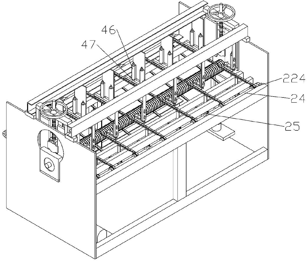
[0047] The difference from the above embodiment is that the bottom of the inner stay is also connected with a lower stay 221, and the bottom of the lower stay is connected with a tensioning sprocket 222 through a slotted hole along the height direction. It is wound on the tension wheel and adjusts the tension of the conveyor chain by adjusting the tension wheel up and down.

[0048] The conveyor chain has no rigidity as a whole, and the inner stays are required to support the part that needs to be supported by steel to ensure the rigidity and horizontal transmission of the plate. The conveyor chain will not hit the front and rear ends of the inner stays to cause failure. The setting of the tensioning sprocket is convenient for disassembly and maintenance of the conveyor chain.

[0049] The chain link cover includes a support surface and side cover surfaces located on both sides of the support surface for respectively connecting with two sides of the chain link, and there is a...

Embodiment 3

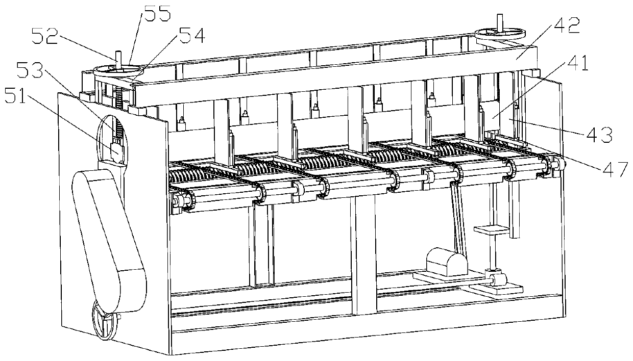
[0051] The difference from the above embodiments is that the auxiliary platen assembly includes a main pressure roller 41 arranged above the long saw shaft and auxiliary import and export components arranged on the front side and / or rear side of the main pressure roller. The import and export parts include a main girder 42 erected on the end frame part, a plurality of suspenders 43 suspended on the main girder and corresponding to the conveying chain one by one, and the bottom of the suspender along the The auxiliary wheel mounting seat 44 provided in the length direction of the conveying chain and the auxiliary wheel 45 arranged on the auxiliary wheel mounting seat; The matching connection of the adjustment rod 46 can adjustably connect the suspension rod up and down. The auxiliary wheel adjustment rod is a hollow tube with a pressure spring inside. The auxiliary wheel mounting seat passes through the hollow tube The suspension shaft 47 is connected to the auxiliary wheel adj...


PUM


Abstract

The invention belongs to the field of floors, and particularly relates to a plate grooving machine. The plate grooving machine comprises a rack, a plate grooving saw structure and a plate conveying structure, wherein the plate grooving saw structure and the plate conveying structure are arranged on the rack. The plate grooving saw structure comprises a long saw shaft, saw blades and a drive shaftmotor. The plate conveying structure comprises a plurality of conveying chain assemblies, auxiliary pressing plate assemblies and a transmission motor, a plate channel is arranged between the auxiliary pressing plate assemblies and the conveying chain assemblies, the auxiliary pressing plate assemblies are located above the conveying chain assemblies, and inner supporting strips are lined on the conveying chain assemblies. The plate grooving machine overturns the device principle of a traditional grooving machine, plates are stably conveyed to the positions of the saw blades for grooving in the mode that bottom grooving is conducted on the plates, the plates are pressed and bottom conveying chains push the plates through a baffle element, the problem that small plates cannot be grooved through upper and lower pure friction force transmission is solved, and the plate grooving machine is suitable for grooving of the small plates and also suitable for grooving of large plates.

Description

technical field [0001] The invention belongs to the field of flooring, and in particular relates to a board slotting machine. Background technique [0002] The existing floor needs to be grooved on the surface of the floor because of some requirements. The traditional groover is to cut grooves on the top of the fed floor by sawing, and the transmission method is mainly through the top conveyor roller pressing against the bottom conveyor belt. The plate is fed into the equipment by friction. This transmission method is only suitable for the transmission of large plates with long grooves. Once the small plate is fed in, due to the limited contact with the conveying roller and the limited friction, the plate cannot be moved on both sides. The balanced force at the end causes the saw blade to be lifted up or pushed back when slotting, so the existing slotting machine cannot perform efficient slotting on narrow and small plates. Contents of the invention [0003] The object of...

Claims


Application Information

Patent Timeline
Patent Type & Authority Applications(China)
IPC IPC(8): B27B5/08B27B5/24B27B5/29B27M3/04B28D1/04B28D7/00B28D7/04
CPCB27B5/08B27B5/24B27B5/29B27M3/04B28D1/04B28D7/00B28D7/043
Inventor 高善柱
Owner 浙江汇杰力木业有限公司
Why Eureka
Try Eureka