Super-deep underground continuous wall and construction method thereof

A technology of underground diaphragm wall and construction method, which is applied in the direction of sheet pile wall, foundation structure engineering, construction, etc., to achieve the effect of excellent groove quality, fast and efficient groove formation, and high efficiency

Inactive Publication Date: 2014-07-23
ZHONGDING INT ENG
View PDF6 Cites 14 Cited by
  • Summary
  • Abstract
  • Description
  • Claims
  • Application Information

AI Technical Summary

Problems solved by technology

[0003] Aiming at the above-mentioned technical problem of trough formation of ultra-deep underground continuous wall under the complex geological conditions of interlaced soft and hard soil, the present invention discloses an ultra-deep underground continuous wall. There are guide walls symmetrically arranged on both sides of the wall. The cross-sectional shape of the guide wall is "L". The lower end of the guide wall is located on the underground rock and soil, and the ears of the guide wall are connected to the concrete road surface.

Method used


Image

  • Super-deep underground continuous wall and construction method thereof
  • Super-deep underground continuous wall and construction method thereof
  • Super-deep underground continuous wall and construction method thereof

Examples


Embodiment Construction

[0024] The specific implementation manners of the present invention will be described below in conjunction with the accompanying drawings.

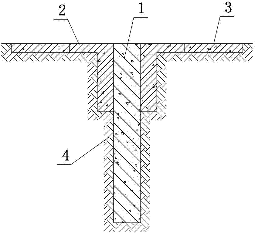
[0025] The ultra-deep underground diaphragm wall, the specific plan is: include a diaphragm wall body 1, and guide walls 2 are symmetrically arranged on both sides of the wall body 1, the cross-sectional shape of the guide wall is "L", and the lower end of the guide wall is located at 4 On the underground rock and soil, the ear side of the guide wall is connected with the concrete pavement 3 . Concrete pavement 3 has a width of 9m, a gravel base layer with a thickness of 200mm, and 50mm gravel on it, and a surface layer of C25 concrete with a thickness of 200mm. Both are 250mm. The width of the guide wall is 40mm wider than the design width d of the continuous wall, and the height of the guide wall is ≥1500mm. The distance between them is 300mm, and the guide wall is provided with a 200mm chamfer at the corner.

[0026] The invention a...


PUM


Abstract

The invention relates to a super-deep underground continuous wall which comprises an underground continuous wall body. Guide walls are symmetrically arranged on the two sides of the wall body, the cross sections of the guide walls are in the shape of an L, the lower ends of the guide walls are located on underground rock-soil, and the lug edges of the guide walls are connected with a concrete pavement. The invention further discloses a construction method of the super-deep underground continuous wall. The method includes the following steps of construction preparation, measuring, guide wall manufacturing, wall protection slurry manufacturing, grooving construction, bottom-clearing replacement, connector cleaning through wall brushing and unit slot section inspection, wherein a grabbing-milling integrated grooving method is used in the grooving construction. The method is high in grooving efficiency, short in construction time and short in groove wall soaking time, the grabbing-milling integrated grooving method is used in the grooving construction, technologies can be changed timely according to different stratum hardness situations, the characteristics that a grab bucket is high in digging speed at the soft soil layer and milling wheel can achieve rapid milling and digging footage at a hard soil layer or bed rod with standard penetration test blow count exceeding 45 are fully used, and therefore rapid and efficient grooving of the whole wall can be achieved.

Description

technical field [0001] The invention relates to an enclosure structure in the technical field of foundation pit engineering, in particular to an ultra-deep underground continuous wall. The present invention also relates to a construction method in the technical field of foundation pit engineering, in particular to a construction method for implementing the above-mentioned ultra-deep underground diaphragm wall. Background technique [0002] With the rapid development of social economy and urban construction, a large number of underground buildings such as intercity high-speed railways, subways, tunnels, underground garages, and underground shopping malls have been built, making the building foundation pit enclosure system bigger and deeper, while southern cities Most of the typical geological conditions are soft soil formations, which are mainly composed of silty clay and silty soil mixed with bedrock. The depth of the bedrock is relatively deep, resulting in the design depth...

Claims


Application Information

Patent Timeline
Patent Type & Authority Applications(China)
IPC IPC(8): E02D5/20
Inventor 陆志东李鸿歆叶小良邓国军张强
Owner ZHONGDING INT ENG
Why Eureka
Try Eureka