Cleaning method of underground anchor rod during underground continuous walls construction

The technology of an underground diaphragm wall and a cleaning method is applied in the field of multi-layer bolt cleaning, which can solve the problems of increasing construction investment, large disturbance of the soil body of the groove wall of the underground diaphragm wall, and affecting the construction progress, etc., and overcomes the slow construction progress, Good wall forming effect, fast and efficient groove forming effect

Inactive Publication Date: 2011-11-16
ZHONGTIAN CONSTR GROUP
View PDF0 Cites 0 Cited by
  • Summary
  • Abstract
  • Description
  • Claims
  • Application Information

AI Technical Summary

Problems solved by technology

In the past, one of the solutions was to backfill gravel first and then erect impact drill punching bolts, which greatly disturbed the soil of the underground diaphragm wall groove wall and required a large amount of backfill cement soil for secondary groove formation operations; the other The method is that when the number of bolt layers is small and shallow, large-scale excavation is adopted, and cement soil is backfilled after breaking the bolts, and the second trenching operation is carried out, which increases construction investment and affects the smooth progress of construction progress.

Method used


Image

  • Cleaning method of underground anchor rod during underground continuous walls construction
  • Cleaning method of underground anchor rod during underground continuous walls construction
  • Cleaning method of underground anchor rod during underground continuous walls construction

Examples


Embodiment Construction

[0028] Below with reference to accompanying drawing, describe the specific implementation steps of the present invention:

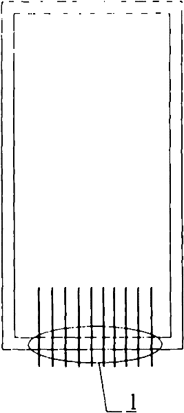
[0029] 1) Organize and analyze the original construction data of the underground anchor bolts within the scope of the construction site, and delineate the construction scope of the underground diaphragm wall trenching (see 1 figure 1 ).

[0030] 2) Through the trial production of underground anchor rod samples, conduct hydraulic shear tests at the groove forming machine manufacturer, analyze various possible conditions, and determine the shear parameters.

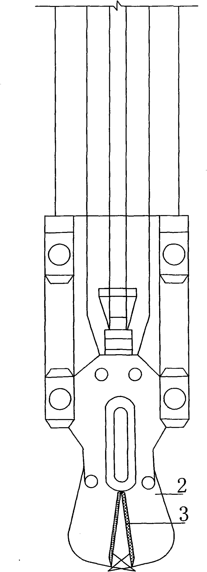
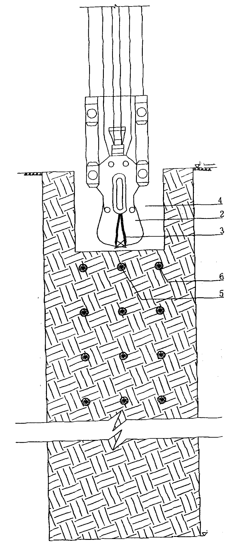
[0031] 3) Weld tungsten steel sheets 3 with good toughness and wear resistance on both sides of the hydraulic grab side plate 2 of the hydraulic grooving machine (see figure 2 ), transported to the site, reinstalled on the site and can carry out trial shearing on the hydraulic grooving machine that needs to be carried out.

[0032] 4) After the trial shearing is passed, determine the reasonable shea...


PUM


Abstract

The invention relates to a cleaning method of underground anchor rods during underground diaphragm walls construction. The cleaning method comprises the following steps of: defining grooving construction ranges of the underground diaphragm walls, determining shearing parameters, adding tungsten-welded steel sheets to two sides of the side plate of a hydraulic crab bucket of a hydraulic grooving machine, tying to shear, carrying out actual operation according to predefined operation range from middle to two sides, and gradually destroying the underground multiple-layer anchor rods; sequentially and symmetrically carrying out the shearing operation of the anchor rods at two sides after the anchor rod of the upper layer is sheared, destroying the anchor rod of the lower layer after the influencing anchor rods of the groove section and the adjacent groove sections are confirmed to be completely eliminated, repeating the process until each layer of anchor rod necessary for cleaning is completely eliminated, then cleaning bottom of hole at the upside, carrying out the construction on the earthwork of the lower layer according to the method from two sides to middle and grooving, testing by ultrasonic waves without errors, and carrying out subsequent construction process of the underground diaphragm walls. In the invention, after soils are borrowed, rubbles are unnecessarily backfilled, and the soil cement is unnecessarily backfilled to carry out the secondary grooving operation. By adopting the invention, groove can be formed quickly and efficiently, the wall formation effects are favorable, the cost is low and the economic benefit is high.

Description

technical field [0001] The invention relates to a method for cleaning underground anchor rods encountered during groove-forming construction of an underground continuous wall, in particular to a cleaning method for multi-layer anchor rods. Background technique [0002] There are more and more cases of underground anchor rods encountered in the construction of underground diaphragm walls adjacent to existing buildings, and the cleaning of multi-layer anchor rods is a complicated construction problem. In the past, one of the solutions was to backfill gravel first and then erect impact drill punching bolts, which greatly disturbed the soil of the underground diaphragm wall groove wall and required a large amount of backfill cement soil for secondary groove formation operations; the other The method is that when the number of bolt layers is small and shallow, large-scale excavation is adopted, and cement soil is backfilled after breaking the bolts, and the second trenching opera...

Claims


Application Information

Patent Timeline
Patent Type & Authority Patents(China)
IPC IPC(8): E02D9/00
Inventor 吴海涛蒋金生方忠民陈恩成刘玉涛王尔
Owner ZHONGTIAN CONSTR GROUP
Why Eureka
Try Eureka