
Logistics unpowered roller turning conveying device

A technology of conveying device and power roller, applied in the direction of roller table, conveyor objects, transportation and packaging, etc., can solve the problems of increasing the friction between the goods and the skateboard, damage to the surface of the goods, and increasing the scrap rate, etc., to prevent separation from the conveying device. , Easy replacement and maintenance, simple and convenient disassembly and assembly

Inactive Publication Date: 2020-01-24
长兴正力物流设备有限公司
View PDF0 Cites 3 Cited by
  • Summary
  • Abstract
  • Description
  • Claims
  • Application Information

AI Technical Summary

Problems solved by technology

[0002] The unpowered roller table is also called the unpowered roller table conveyor. The roller table can be divided into a powered roller table and an unpowered roller table according to whether there is power or not. Its working principle is that people push and pull the workpiece or squeeze the workpiece. Moving on the rollers, the unpowered roller table can greatly reduce the intensity of handling, loading and unloading, and improve work efficiency. It can be used alone or in any combination. It can be easily transported regardless of the weight and size of the item. The unpowered roller Conveyors often need to turn during logistics transportation. In order to ensure the smooth completion of the turn of the goods, the traditional turning conveyor sets slide plates on both sides, so that the goods slide along the slide plates on both sides, and then completes the turn. The centrifugal force will increase the friction between the goods and the skateboard, which will cause damage to the surface of the goods. At the same time, when the goods touch the skateboard for a moment, an impact force will be generated. The vibration generated by the impact force will damage the goods again, thereby increasing the scrap rate.

Method used


Image

  • Logistics unpowered roller turning conveying device
  • Logistics unpowered roller turning conveying device
  • Logistics unpowered roller turning conveying device

Examples


Embodiment Construction

[0024] In order to make the technical means, creative features, goals and effects achieved by the present invention easy to understand, the present invention will be further described below in conjunction with specific embodiments.

[0025] In the description of the present invention, it should be noted that the terms "upper", "lower", "inner", "outer", "front end", "rear end", "both ends", "one end", "another end" The orientation or positional relationship indicated by etc. is based on the orientation or positional relationship shown in the drawings, and is only for the convenience of describing the present invention and simplifying the description, rather than indicating or implying that the referred device or element must have a specific orientation, use a specific Azimuth configuration and operation, therefore, should not be construed as limiting the invention. In addition, the terms "first" and "second" are used for descriptive purposes only, and should not be understood ...


PUM


Abstract

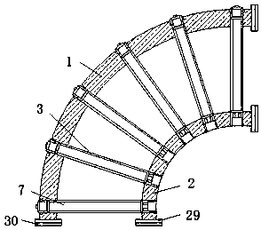
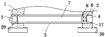
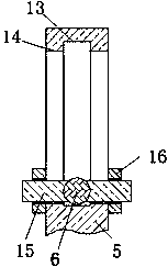
The invention discloses a logistics unpowered roller turning conveying device. The device comprises a first arc-shaped fixing plate and a second arc-shaped fixing plate, wherein the top ends of the first arc-shaped fixing plate and the second arc-shaped fixing plate are connected through a plurality of supporting plates, supporting columns and arc-shaped supporting plates are symmetrically arranged on the two sides of the top ends of the supporting plates, and the supporting columns and the arc-shaped supporting plates are fixedly connected with the supporting plates; fixing shafts are arranged between the supporting columns and the arc-shaped supporting plates, two limiting plates are symmetrically arranged on the outer portion of each fixing shaft in a sleeving mode, and the outer portion of each fixing shaft is provided with a roller located between the two limiting plates in the sleeving mode. According to the logistics unpowered roller turning conveying device, the inclination angle of each roller can be flexibly adjusted according to actual needs, so that the goods position deviation caused by centrifugal force is effectively prevented; and goods can stably slide on the rollers without the arrangement of a sliding plate, and the goods are prevented from being damaged while the goods are prevented from separating from the conveying device.

Description

technical field [0001] The invention relates to the technical field of roller table turning and conveying, in particular to a logistics unpowered roller table turning conveying device. Background technique [0002] The unpowered roller table is also called the unpowered roller table conveyor. The roller table can be divided into a powered roller table and an unpowered roller table according to whether there is power or not. Its working principle is that people push and pull the workpiece or squeeze the workpiece. Moving on the rollers, the unpowered roller table can greatly reduce the intensity of handling, loading and unloading, and improve work efficiency. It can be used alone or in any combination. It can be easily transported regardless of the weight and size of the item. The unpowered roller Conveyors often need to turn during logistics transportation. In order to ensure the smooth completion of the turn of the goods, the traditional turning conveyor sets slide plates o...

Claims


Application Information

Patent Timeline
Patent Type & Authority Applications(China)
IPC IPC(8): B65G13/08B65G39/02
CPCB65G13/08B65G39/02
Inventor 丁梦清
Owner 长兴正力物流设备有限公司
Learn More