
Armored vehicle wheel fixing and checking device with positioning mechanism

A positioning mechanism and inspection device technology, applied in lifting devices, vehicle maintenance, transportation and packaging, etc., can solve the problems of inability to perform position positioning operations of armored vehicles, inability to disassemble and lift wheels, etc., and achieve simple adjustment and disassembly methods , easy to carry, increase the effect of the structure

Inactive Publication Date: 2020-01-24
DONGGUAN UNIV OF TECH
View PDF7 Cites 1 Cited by
  • Summary
  • Abstract
  • Description
  • Claims
  • Application Information

AI Technical Summary

Problems solved by technology

[0004] Aiming at the deficiencies of the prior art, the present invention provides a fixed inspection device for armored vehicle rollers with a positioning mechanism, which solves the problem in the above-mentioned background technology that the armored vehicle needs to be maintained and overhauled after it has been used for a long time, especially the problem of armored vehicles. For the chassis part, most of the existing inspection devices move the armored vehicle to the lifting platform, and then inspect and maintain the bottom of the armored vehicle. The movement of the armored vehicle can only rely on the driver's personal skills, and it is impossible to locate the position of the armored vehicle. The platform can only maintain the chassis, but cannot disassemble and upgrade individual wheels, and cannot meet people's needs and other issues.

Method used


Image

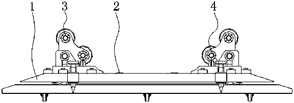
  • Armored vehicle wheel fixing and checking device with positioning mechanism
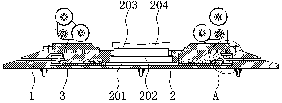
  • Armored vehicle wheel fixing and checking device with positioning mechanism
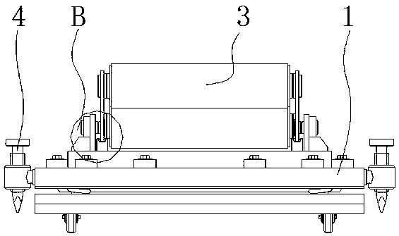
  • Armored vehicle wheel fixing and checking device with positioning mechanism

Examples


Embodiment Construction

[0027] The following will clearly and completely describe the technical solutions in the embodiments of the present invention with reference to the accompanying drawings in the embodiments of the present invention. Obviously, the described embodiments are only some, not all, embodiments of the present invention.

[0028] In the description of the present invention, unless otherwise stated, the meaning of "plurality" is two or more; the terms "upper", "lower", "left", "right", "inner", "outer" , "front end", "rear end", "head", "tail", etc. indicate the orientation or positional relationship based on the orientation or positional relationship shown in the drawings, and are only for the convenience of describing the present invention and simplifying the description, rather than Indicates or implies that the device or element referred to must have a particular orientation, be constructed and operate in a particular orientation, and therefore should not be construed as limiting the...


PUM


Abstract

The invention discloses an armored vehicle wheel fixing and checking device with a positioning mechanism and relates to the technical field of armored vehicle checking devices, in particular to the armored vehicle wheel fixing and checking device with the positioning mechanism. The armored vehicle wheel fixing and checking device comprises a combined base and auxiliary rotating devices. A load bearing device is arranged in the middle of the combined base. The end, close to the center axis of a fixed base, of each fixed rotary shaft is provided with a movable clamping plate. The service performance of the whole armored vehicle wheel fixing and checking device with the positioning mechanism is greatly improved while the structure is added. Through the improved device, the frequent using frequency of a large lifting platform can be reduced. The armored vehicle wheel fixing and checking device is easier and more convenient to use. The carrying capacity of an armored vehicle is improved. Moreover, when the armored vehicle wheel fixing and checking device with the positioning mechanism is in use, the armored vehicle can be positioned, and the difficulty of a driver driving the armored vehicle is reduced. Meanwhile, through the armored vehicle wheel fixing and checking device, any independent armored vehicle tire can be supported, disassembled, assembled and replaced conveniently. Theusage requirements of people are met effectively.

Description

technical field [0001] The invention relates to the technical field of armored vehicle inspection devices, in particular to an armored vehicle roller fixing inspection device with a positioning mechanism. Background technique [0002] Armored vehicles are various tracked or wheeled military vehicles with armor protection. They are a general term for armored military or police vehicles. Tanks are also a type of tracked armored vehicles, but they are usually classified independently for combat purposes. , and armored vehicles mostly refer to vehicles with weaker protection and firepower than tanks. Armored vehicles are characterized by high off-road maneuverability, certain protection and firepower, and are divided into two types: tracked and wheeled. Two small and medium-caliber artillery pieces and several machine guns, some of which are also equipped with anti-tank missiles. The structure is composed of an armored body, a weapon system, and a power plant. [0003] However,...

Claims


Application Information

Patent Timeline
IPC IPC(8): B66F5/04B66F13/00B60S5/00
CPCB60S5/00B66F5/04B66F13/00
Inventor 邓君陈奕傧李川
Owner DONGGUAN UNIV OF TECH
Learn More