
Steel pipe concrete column H-shaped steel beam fabricated rigid joint strong beam strong column structure and construction method

A technology of steel tube concrete column and H-shaped steel, which is applied in the direction of building structure, construction, etc., can solve the problems of small rigidity and non-directionality, and achieve the effect of high bearing capacity, large extension length, and strengthened cooperative work

Active Publication Date: 2020-01-24
CENT SOUTH UNIV
View PDF4 Cites 0 Cited by
  • Summary
  • Abstract
  • Description
  • Claims
  • Application Information

AI Technical Summary

Problems solved by technology

A ring-shaped reinforced concrete beam is poured around the steel pipe column to transmit bending moment and shear force. The advantage is that it has no direction, that is, it can be connected with the floor in any direction. The disadvantage is that the rigidity is small

Method used


Image

  • Steel pipe concrete column H-shaped steel beam fabricated rigid joint strong beam strong column structure and construction method
  • Steel pipe concrete column H-shaped steel beam fabricated rigid joint strong beam strong column structure and construction method
  • Steel pipe concrete column H-shaped steel beam fabricated rigid joint strong beam strong column structure and construction method

Examples


Embodiment Construction

[0072] In order to better understand the present invention, the invention will be described in further detail below in conjunction with the accompanying drawings and implementation examples, but the implementation of the present invention is not limited thereto, and the scope of protection of the present invention is also designed by those skilled in the art according to the concept of the present invention. Think of the equivalent technical means.

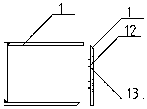
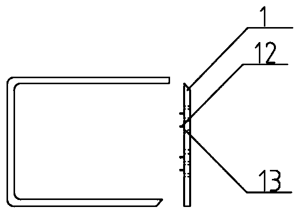
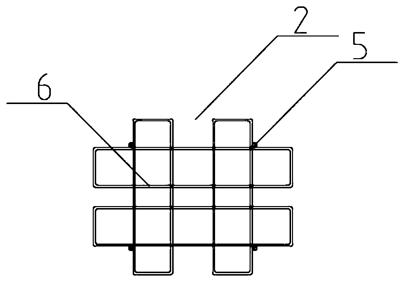
[0073] Figure 1 to Figure 18 As shown, a concrete-filled steel tube column H-shaped steel beam assembled rigid-connected node strong beam-strong column structure includes a steel tube concrete column with tension bars, an assembled rigid strong node and an H-shaped steel beam.

[0074] In order to better understand the present invention, two examples are now proposed: embodiment 1 is that the node member penetrates the steel plate member, and both the upper and lower node members use H-shaped steel supports; embodiment 2 is that ...


PUM


Abstract

The invention discloses a steel pipe concrete column H-shaped steel beam fabricated rigid joint strong beam strong column structure and a construction method. The steel pipe concrete column H-shaped steel beam fabricated rigid joint strong beam strong column structure comprises steel plate components, wherein the steel plate components are arranged at column beam joints and are welded to steel pipes of steel pipe concrete columns, joint components are welded to the connecting surfaces of the steel plate components and H-shaped steel beams, the joint components comprise upper part strutting pieces, lower part strutting pieces and web connecting pieces, the web connecting pieces are arranged between the upper part strutting pieces and the lower part strutting pieces, gaps matched with the flange thickness of the H-shaped steel beams are formed between the web connecting pieces and the upper part strutting pieces and between the web connecting pieces and the lower part strutting pieces, high-strength bolt holes corresponding to the H-shaped steel beams are formed in the flanges of the opposite faces of the upper part strutting pieces and the lower part strutting pieces, and the high-strength bolt holes corresponding to the H-shaped steel beams are formed in the web connecting pieces. According to the steel pipe concrete column H-shaped steel beam fabricated rigid joint strong beamstrong column structure and the construction method thereof, two-way split stirrups are utilized, so that the defects of insufficient constraint effect and buckling of steel pipes are overcome, strutting pieces are arranged at the beam column joints, so that the bearing capacity of the hogging moment area of beam ends can be effectively improved, and the whole joints are definite in force transmission and good in overall performance.

Description

technical field [0001] The invention belongs to the field of construction engineering structures, and relates to a steel pipe concrete column H-shaped steel beam assembly type rigid joint joint strong beam strong column structure and a construction method. Background technique [0002] The concrete structure has better integrity, durability and fire resistance, but poor bending and shear resistance, and is prone to brittle failure; the steel structure has high material strength, light weight, good plastic toughness, and poor fire resistance and corrosion resistance. The concrete-filled steel tube structure is evolved and developed on the basis of steel-shaped concrete structure, spiral-reinforced reinforced concrete structure and steel structure. Concrete-filled steel tube can take advantage of the advantages of both concrete and steel structures at the same time, and the interaction between the two can overcome the two The shortcomings of the material itself. Concrete fill...

Claims


Application Information

Patent Timeline
Patent Type & Authority Applications(China)
IPC IPC(8): E04B1/30E04B1/58
CPCE04B1/185E04B1/30
Inventor 丁发兴王恩王莉萍吕飞余玉洁
Owner CENT SOUTH UNIV
Learn More