LED light source module and production method thereof

A technology of LED light source and module, which is applied in the direction of light source, light source fixation, semiconductor devices of light-emitting elements, etc., which can solve the difficulties of high reliability, low-cost production and manufacturing, increase the complexity of light source module circuit, and soft extrusion type Problems such as deformation of plastic parts, to achieve high yield rate, convenient engineering installation and use, and improve the effect of waterproofing

Active Publication Date: 2021-09-21
深圳市熠鸿光电科技有限公司
View PDF16 Cites 0 Cited by
  • Summary
  • Abstract
  • Description
  • Claims
  • Application Information

AI Technical Summary

Problems solved by technology

Its shortcomings are: using constant current source power supply: the number of light source modules in series must match the power supply and when a light source module is open, its back end will lose power, which greatly limits the application in engineering
[0006] 2. Add a constant voltage or constant current circuit to each light source module to ensure the input power of the light source module, and then use a higher power supply voltage to supply multiple light source modules connected in series in parallel. This structure increases the power of the light source. The circuit complexity of the module reduces reliability and adds higher cost
[0010] 1) The light source module string is both a small-volume product and a mass-produced product. It is extremely difficult to pass several or even one wire through the light source module string and produce it with high efficiency, high reliability, low cost, and even automation.
[0011] 2) In the process of automated mass production, there is a problem of accurate docking and positioning of wires and pads on the circuit board
[0013] a. Soft extruded plastic parts are easily deformed due to stacking and extrusion during storage
[0014] b. Plugs that need to be installed separately or injection molded at both ends of the light source module, the product consistency is poor when installed manually, and it is not beautiful
And it is difficult to manufacture when special shapes such as squares, polygons, circles, etc. are required

Method used


Image

  • LED light source module and production method thereof
  • LED light source module and production method thereof
  • LED light source module and production method thereof

Examples


Embodiment 1

[0104] 1. The specific structure is:

[0105] 1) The housing 1 is hard or soft.

[0106] 2) The circuit board 6 is a hard board or a flexible board.

[0107] 3) The positive and negative wires 4 are located on the upper surface of the circuit board 6 .

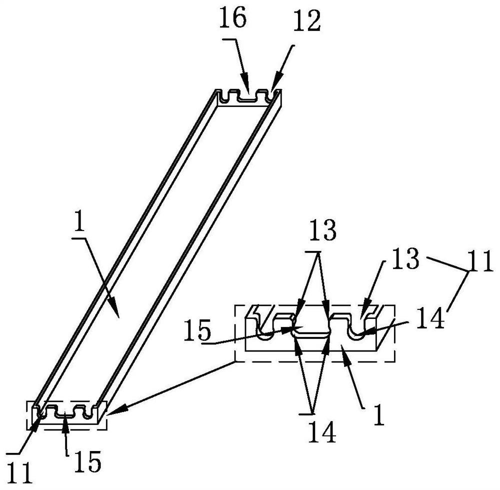
[0108] 4) The wire inlet hole 11 and the wire outlet hole 12 are hourglass type wire holes 13 .

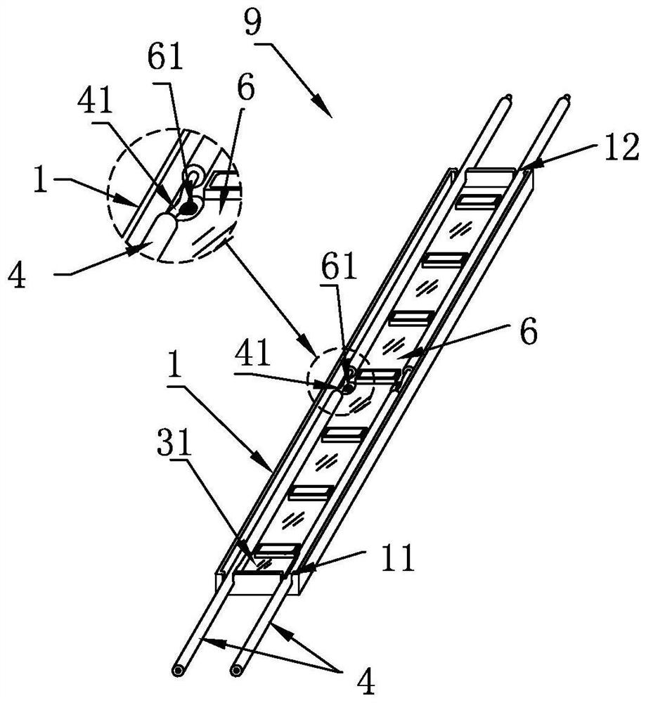
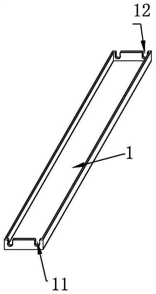
[0109] Such as figure 1 , Figure 1a , Figure 1b As shown, the positive and negative wires 4 come in and out from the wire inlet holes 11 and wire outlet holes 12 at both ends of the housing 1, and are placed and fixed above the circuit board 6. The conductive part 41 on the wires forms a "V" shape or a "U" shape during assembly. " shape is bent, and the opening of "V" shape or "U" shape faces upwards, and the bottom of the bend touches or approaches the conductive plate 61 (also known as the pad, the so-called "approaching" is the conductive part 41 arranged on the circuit board 6 The distance between the lower end point o...

Embodiment 2

[0124] 1. Specific structure

[0125] 1) The housing 1 is hard or soft.

[0126] 2) The circuit board 6 is a hard board or a flexible board, on which an IC control chip is arranged.

[0127] 3) The positive and negative wires 4 are located on the sides of the circuit board 6 , and the positive and negative wires are preferably separated and located on both sides of the circuit board 6 .

[0128] 4) The wire inlet hole 11 , the wire outlet hole 12 , the wire inlet window hole 15 and the wire outlet window hole 16 are all hourglass type wire passage openings 13 .

[0129] Such as figure 2 , Figure 2a , Figure 2b , Figure 2c As shown, in actual application, in order to realize that each LED light source module 9 in a string of LED light source modules 9 can be individually controlled, IC chips and other components will be added to the circuit of the LED light source module 9, at this time , the positive and negative wires 4 placed above the circuit board 6 will affect t...

Embodiment 3

[0135] 1. Specific structure

[0136] 1) The housing 1 is soft.

[0137] 2) The circuit board 6 is a hard board or a flexible board.

[0138] 3) The positive and negative wires 4 are arranged in the wire groove under the circuit board 6 .

[0139] 4) The conductive plate 61 on the circuit board 6 is an open soldering plate.

[0140] 5) The wire inlet hole 11 and the wire outlet hole 12 are slit type wire holes 13 .

[0141] Such as image 3 , Figure 3a , Figure 3b , Figure 3c As shown, when the wire diameters of the positive and negative wires 4 are large, in order to prevent the potting compound from covering the light-emitting surface of the lamp bead and affecting the purity of the light color, the potting compound may be filled thinner, so that the adhesive layer cannot fully Covering the exposed conductive part 41 (of course, this situation is possible when the waterproof requirement above IP65 is not required), results in poor waterproof performance. In order ...


PUM


Abstract

An LED light source module and a production method thereof. Its shell is an enclosed box with an open top surface enclosed by side walls and a bottom plate. A small section of insulation layer on the positive and negative wires placed in the enclosed box is stripped to a bare wire core, and the exposed wire core is folded. Bend into a "V" shape or "U" shape conductive part, the conductive part is electrically connected with the conductive plate on the circuit board by welding or clamping. It fixes the circuit board in the concave cavity of the enclosure, and uses potting glue or sealant to cover the wires, signal control lines, and exposed solder joints on the circuit board. This structure can make the dustproof and waterproof grade of the LED light source module reach IP68 grade. The use of tightening and positioning the wire inlet and outlet holes can greatly improve the alignment accuracy of the conductive part on the wire and the conductive plate on the circuit board. the height of the point. The power transmission loss of the light source module is small, the production is simple, and the efficiency and yield rate are high.

Description

technical field [0001] The invention relates to an LED light source module, in particular to an LED light source module string and an automatic production method thereof. Background technique [0002] In the fields of landscape lighting, lighting, decoration, etc., LED point light source modules are often used to arrange a large number of light strips or dots in the form of lines according to demand, that is, several LED light source modules are connected in series for use. [0003] In the actual application of the above structure, the light source module far away from the power supply terminal will cause a large voltage drop due to line loss, resulting in insufficient brightness. In order to solve this problem, the form of multi-point power supply has to be used during installation, but it will cause difficulties in construction, wiring, etc., and increase the cost. [0004] In the field of light source module production, in order to solve the problem of as many serial con...

Claims


Application Information

Patent Timeline
Patent Type & Authority Patents(China)
IPC IPC(8): F21K9/20F21K9/90F21V19/00F21V23/06F21V31/04F21Y115/10
CPCF21K9/90F21V19/001F21V23/06F21V31/04F21K9/20F21Y2115/10
Inventor 朱耀
Owner 深圳市熠鸿光电科技有限公司
Why Eureka
Try Eureka