Deep seismic energy conversion and utilization device in pile foundation and operation method

A deep, pile-based technology, applied in the field of power generation devices, can solve the problems of fossil fuel environmental problems that cannot be solved, no seismic collection and utilization, loss of utilization value, etc., to save the available space of buildings, improve energy conversion efficiency, and realize energy And the effect of energy conversion utilization

Pending Publication Date: 2020-05-19
ZHEJIANG UNIVERSITY OF SCIENCE AND TECHNOLOGY
View PDF0 Cites 0 Cited by
  • Summary
  • Abstract
  • Description
  • Claims
  • Application Information

AI Technical Summary

Problems solved by technology

[0002] Fossil fuels are the main source of energy in the world today, but the environmental problems brought about by the massive use of fossil fuels have not been resolved. Therefore, it is imminent to find a new clean energy
Although earthquakes carry a large amount of vibration energy, there is currently no good way to collect and utilize seismic energy. There are many seismically active zones distributed around the world. How to utilize these seismic energy has become a new topic and challenge
In addition, since the source of earthquakes is usually located deep in the ground, although some small earthquakes also carry huge energy, the loss of energy to the surface is too large and loses its use value

Method used


Image

  • Deep seismic energy conversion and utilization device in pile foundation and operation method
  • Deep seismic energy conversion and utilization device in pile foundation and operation method
  • Deep seismic energy conversion and utilization device in pile foundation and operation method

Examples


Embodiment Construction

[0024] The present invention will be further described below in conjunction with the accompanying drawings.

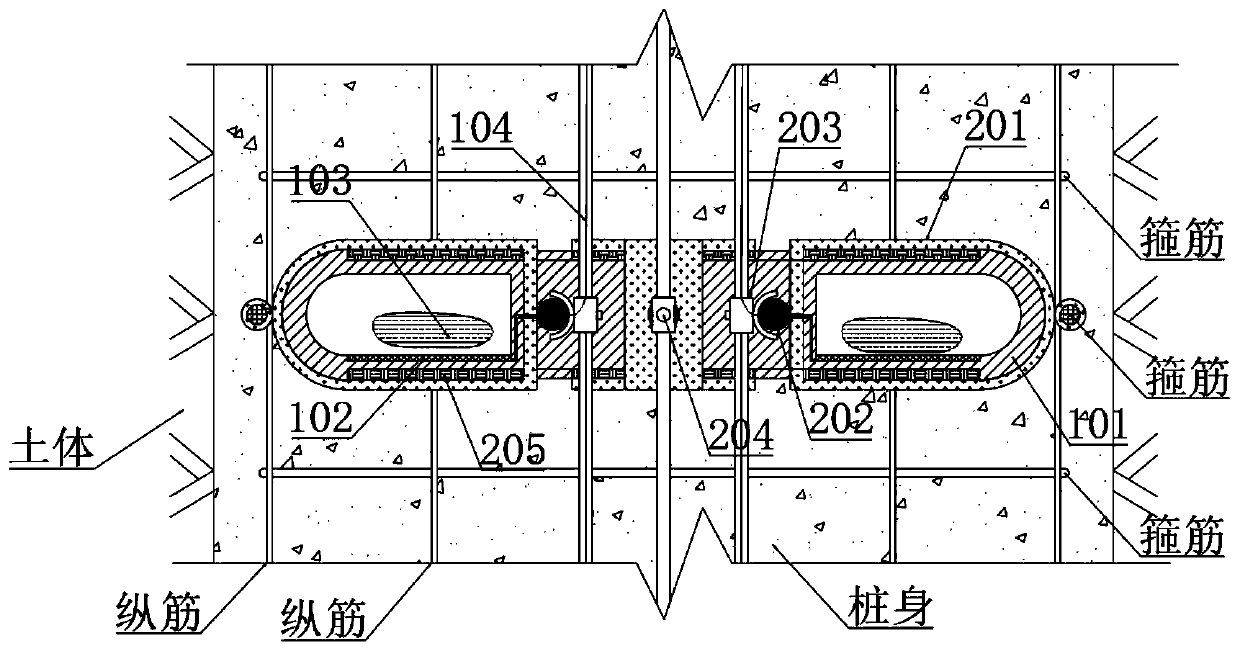
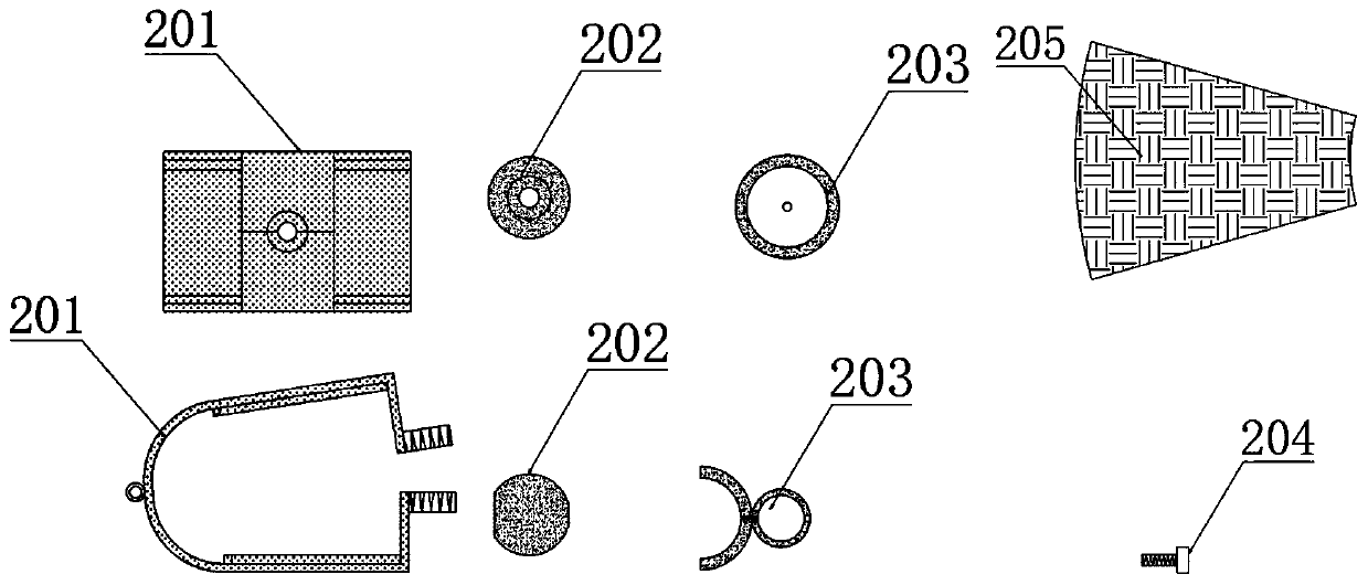
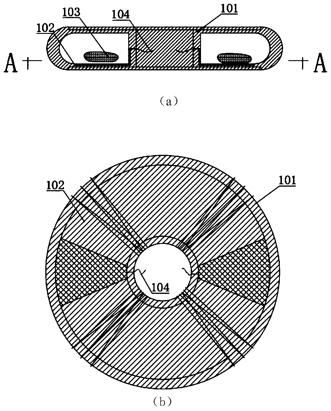
[0025] refer to Figure 1 ~ Figure 4 , a deep seismic energy conversion and utilization device in a pile foundation, comprising a stretchable rubber ring 101, a magnetic fluid 103, an electrode plate 102, a metal clip 201 and a fixing cap 203, the stretchable rubber ring 101 is hollow inside, and its cavity The magnetic fluid 103 is injected into the stretchable rubber ring 101 through the gas valve, the electrode plate 102 is placed on the molding mold of the stretchable rubber ring 101, and the stretchable rubber ring 101 is connected with the stretchable rubber ring. The rubber ring is shaped together and left in the inner cavity of the rubber ring. There are grooves on the top and bottom of the metal clip 201 for installing the sheet magnet 205. The outer side of the metal clip 201 is a ring buckle, and the buckle and The stirrups of the reinforcement cage in the ...


PUM


Abstract

The invention discloses a deep seismic energy conversion and utilization device in a pile foundation. A telescopic rubber ring is hollow, and a cavity of the telescopic rubber ring is connected with the outside through an air valve; magnetic fluid is injected into the telescopic rubber ring through the air valve; an electrode plate is arranged on a shaping mold of the telescopic rubber ring, and is molded together with the telescopic rubber ring and reserved in the cavity of the rubber ring; grooves are formed in the upper and lower parts of metal clamping pieces for mounting sheet magnets; anannular buckle is arranged on the outer side of each metal clamping piece; the buckles are connected with stirrups of a reinforcement cage in a pile; openings of the metal clamping pieces are spiral;the metal clamping pieces are fixed through spherical nuts during installation, fixing caps are buckled on the spherical nuts, reinforcing steel bars or pipelines are inserted into the fixing caps toform a framework or a guide circuit; and the reinforcing steel bars or wire pipes are fixed through the fixing bolts, and wires are led out from the reserved gaps. The invention further provides an operation method of the deep seismic energy conversion and utilization device in the pile foundation. The method is low in cost, high in efficiency and environmentally friendly.

Description

technical field [0001] The invention relates to a power generation device for collecting deep seismic energy and converting it into electric energy. It is installed in various building pile foundations on seismically active zones. device used. Background technique [0002] Fossil fuels are the main energy sources in the world today, but the environmental problems brought about by the massive use of fossil fuels have not been resolved. Therefore, it is urgent to find a new clean energy source. Although earthquakes carry a large amount of vibration energy, there is currently no good way to collect and utilize seismic energy. There are many seismically active zones distributed around the world. How to utilize these seismic energy has become a new topic and challenge. In addition, since the source of earthquakes is usually located deep in the ground, although some small earthquakes also carry huge energy, the loss of energy to the surface is too large, and it is useless. Con...

Claims


Application Information

Patent Timeline
IPC IPC(8): H02K44/08E02D5/34E02D27/34
CPCE02D5/34E02D27/34E02D2250/0023H02K44/08
Inventor 罗战友李晓泉邹宝平朱剑锋陈其志赵昕陶燕丽丁康陈永国吴李泉
Owner ZHEJIANG UNIVERSITY OF SCIENCE AND TECHNOLOGY
Why Eureka
Try Eureka