
Diffuser and flame tube optimal matching experimental research device

A technology of experimental research and flame tube, which is applied in the field of experimental devices for optimal matching of low-loss diffusers and flame tubes. Large-scale, low-flexibility effects

Active Publication Date: 2020-01-24
ZHEJIANG UNIV
View PDF9 Cites 11 Cited by
  • Summary
  • Abstract
  • Description
  • Claims
  • Application Information

AI Technical Summary

Problems solved by technology

[0007] Due to the existence of unsteady flow structures such as flow separation in the flow of the diffuser, the depth of flow details and mechanism research is not enough, the error between the simulation results and the experimental results is relatively large, and the calculation accuracy of the flow loss is too low, which is unacceptable in engineering. Lack of matching optimization design method and evaluation criteria for compressor and flame tube head
At present, most of the relevant research is based on the engine model, and its design structure does not have the ability to flexibly change component parameters, or the cost of changing component parameters is high. The selection of design variables is limited by the engine model data, which has great limitations. Unable to select variables in a large enough range, resulting in insufficient systematic research, and it is difficult to find optimal parameters through experiments. There is no systematic database for reference of different diffuser flow characteristics, and basic research is urgently needed to provide technical support.

Method used


Image

  • Diffuser and flame tube optimal matching experimental research device
  • Diffuser and flame tube optimal matching experimental research device

Examples


Embodiment Construction

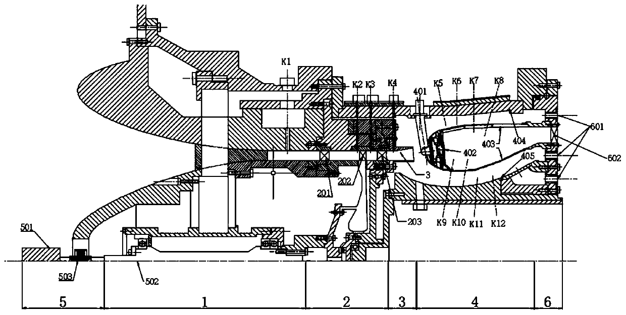
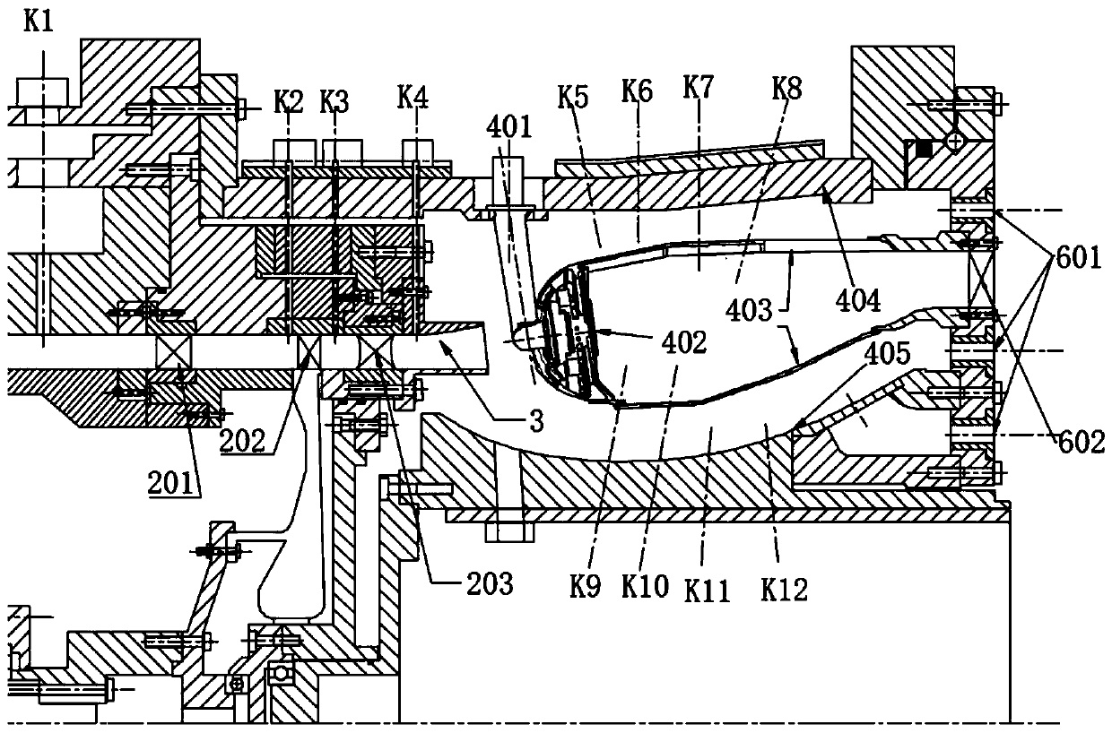
[0036] Reference attached figure 1 , an experimental research device for optimal matching of a diffuser and a flame tube includes an inlet 1 , a compressor 2 , a diffuser 3 , a combustion chamber 4 , an electric drive device 5 and an exhaust port 6 . attached figure 2 It is the air inlet, compressor and combustor part of the gas turbine engine simulated by the present invention.

[0037] An experimental research device for optimal matching of a diffuser and a flame cylinder, comprising:

[0038] Intake channel 1: provides stable air flow for the compressor, located upstream of the core part of the experimental device, provides stable air flow for the compressor, mainly includes an air inlet 101, a rectifying impeller 102, and an air intake channel 103. Among them, the rectifying impeller contains 4 blades in total. There is a measuring hole K1 in the air inlet channel 103, to measure the characteristic parameters of the upstream of the gas flow;

[0039] The compressor 2 ...


PUM


Abstract

The invention discloses a diffuser and flame tube optimal matching experimental research device which comprises an electric driving device, and further comprises an air inlet channel, an air compressor, a diffuser, a combustion chamber and an air outlet which are connected in sequence, and the diffuser and flame tube optimal matching experimental research device is used for simulating the sectionsof the air inlet channel, the air compressor and the combustion chamber of a typical gas turbine engine. The diffuser and flame tube optimal matching experimental research device can flexibly replacedifferent impellers and diffusers to set different inlet parameters for experimental simulation, so that the research of optimal matching between the low-loss diffuser and the flame tube becomes practical. Through the adoption of the diffuser and flame tube optimal matching experimental research device, the relation between an actual upstream inflow condition of the flame tube and the performanceof the flame tube can be researched, the influence rule of diffuser design on the flow field organization, flow distribution and combustion performance of the flame tube and a head is mastered, a low-loss diffuser optimization method and an optimal matching method with the flame tube and the head are formed, and therefore the diffuser and flame tube optimal matching experimental research device is of important significance in realizing advanced combustion organization of the flame tube.

Description

technical field [0001] The invention relates to the field of gas turbine engines, in particular to an experimental device for optimal matching of a low-loss diffuser and a flame cylinder. Background technique [0002] A modern gas turbine aero-engine is mainly composed of an intake, a compressor, a combustion chamber, a turbine, and an exhaust. [0003] The compressor is a part of the gas turbine engine that uses high-speed rotating blades to do work for the air to increase the air pressure. The front part of the compressor impeller blade is curved and called the guide wheel. Its function is to introduce the gas into the working impeller without impact, reducing Small airflow impact loss. The compressor impeller of the small supercharger generally integrates the guide wheel and the working impeller. [0004] The diffuser (diffuser) couples part of the air flow at the outlet of the compressor with the flame tube, so that the kinetic energy obtained by the gas in the impelle...

Claims


Application Information

Patent Timeline
Patent Type & Authority Applications(China)
IPC IPC(8): G01M15/14G01M15/02
CPCG01M15/02G01M15/14
Inventor 王高峰钟亮王崯瞩叶振辉方元祺郑耀
Owner ZHEJIANG UNIV
Learn More