Distribution network automatic control device for power grid dispatching

A distribution network automation and control device technology, applied in the direction of electrical components, etc., can solve problems such as high cost, large electric energy of the switch blade, and difficulty in closing or separating the switch blade

Pending Publication Date: 2020-01-24
李中毅
View PDF12 Cites 0 Cited by
  • Summary
  • Abstract
  • Description
  • Claims
  • Application Information

AI Technical Summary

Problems solved by technology

The distribution network automation equipment for power grid dispatching includes a large number of automatic isolating switches, which are essential switching components in high-voltage lines. The electric drive module in the automatic isolating switch is connected to PLC, and the isolating switch can be controlled by remote control. On and off; while the automatic isolating switch in the existing technology is controlled by the control system to open or close, it is difficult to close or separate the switch knife, and it needs a relatively high-power electric drive to complete; on the one hand, the cost is higher ; On the other hand, the opening and closing of the switch knife consumes a lot of power. For thousands of automatic isolating switches, the total energy consumption is considerable; how to effectively reduce the energy consumption of the automatic isolating switch is the basic One of the important topics studied by technical personnel in the field

Method used


Image

  • Distribution network automatic control device for power grid dispatching
  • Distribution network automatic control device for power grid dispatching
  • Distribution network automatic control device for power grid dispatching

Examples


Embodiment Construction

[0027] The accompanying drawings are schematic diagrams of the implementation of the present invention, so as to facilitate the understanding of the operation principle of the structure. The specific product structure and proportions can be determined according to the use environment and conventional techniques.

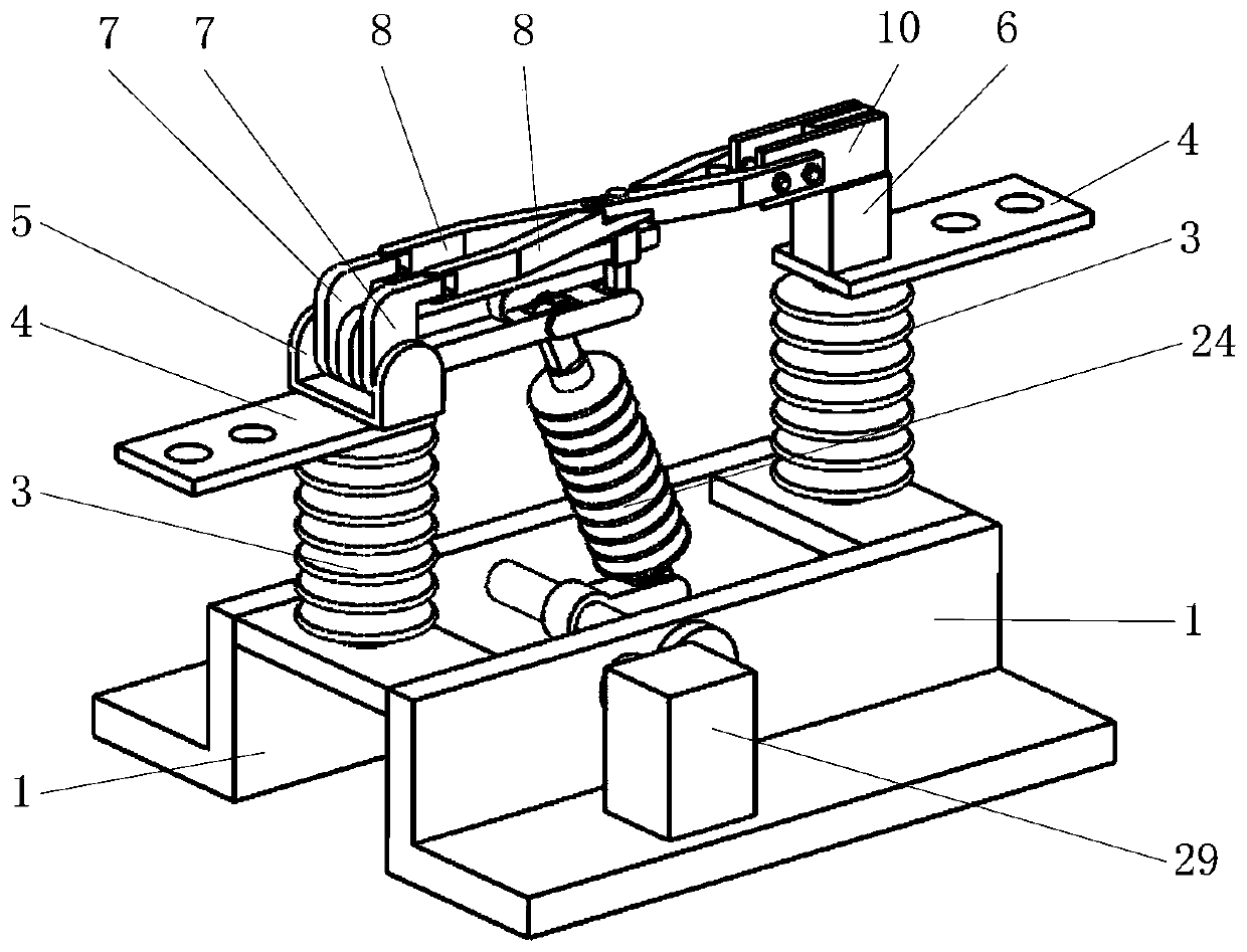
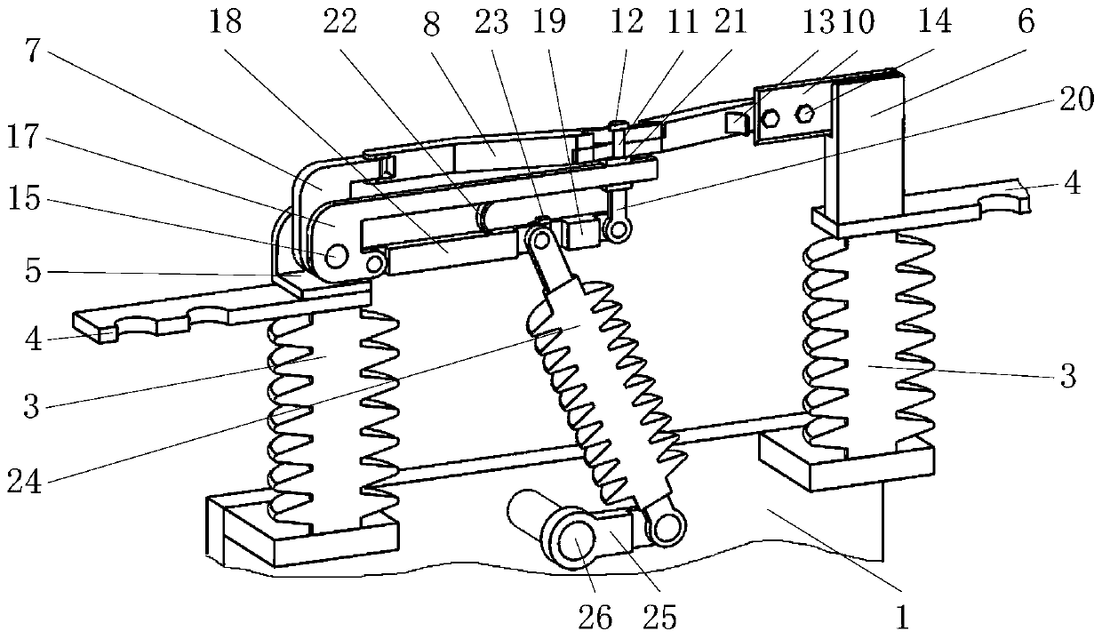
[0028] like figure 1 , 2 As shown, it includes a base 1, an insulator A3, a wiring board 4, an inverted T contact 6, a knife mechanism, an insulator B24, a transmission shaft 26, and a stepping motor 29, among which, such as figure 1 , 2 As shown, two vertical insulators A3 are symmetrically installed on the base 1, and a wiring board 4 with wiring holes is installed on the upper end of each insulator A3; figure 2 As shown, an inverted T contact 6 is installed on one wiring board 4, and a knife mechanism that cooperates with the inverted T contact 6 is installed on the other wiring board 4; figure 1 , 2 As shown, the bearing on the base 1 is equipped with a tra...


PUM


Abstract

The invention belongs to the field of automatic disconnecting switches. The distribution network automatic control device for power grid dispatching comprises a base, insulators A, wiring boards, an inverted T contact, a knife switch mechanism, insulators B, a transmission shaft and a stepping motor; the two vertical insulators A are symmetrically installed on the base; and the wiring boards withwiring holes are installed at the upper ends of the insulators A respectively. According to the distribution network automatic control device for power grid dispatching of the invention, two L-shapedplates A are matched with two external threads with opposite rotating directions at two ends of a pin A respectively; and when two swing plates swing upwards simultaneously along with the L-shaped plates A hinged to the swing plates, the two swing plates of which the middle portions hinged in a crossed mode swing oppositely around a hinged point between the two swing plates, so that two conductiveplates release the clamping of the inverted T-shaped contact and are separated from each other, and therefore, a disconnecting switch is turned on. In a working process, the stepping motor only overcomes the obstruction of a plate spring B with a very small elastic coefficient and breaks a balance-approximating state between the plate spring B and the stepping motor, and the stepping motor consumes less energy and has a better energy-saving effect.

Description

technical field [0001] The invention belongs to the field of automatic isolation switches, in particular to a distribution network automation control device used for grid dispatching. Background technique [0002] Now the pace of urbanization is getting faster and faster, and the development of cities is getting faster and faster, and the consumption of electric energy is getting larger and larger; The distribution network automation equipment is proposed. The distribution network automation equipment for power grid dispatching includes a large number of automatic isolation switches. As an indispensable switch component in high-voltage lines, the electric drive module in the automatic isolation switch is connected to the PLC, and the isolation switch can be realized through remote control. On and off; while the automatic isolation switch in the existing technology is more difficult to close or separate the knife when the control system controls it to open or close, it requi...

Claims


Application Information

Patent Timeline
Patent Type & Authority Applications(China)
IPC IPC(8): H01H21/54H01H21/36H01H21/22
CPCH01H21/22H01H21/36H01H21/54
Inventor 不公告发明人
Owner 李中毅
Why Eureka
Try Eureka