Propeller fan
A technology for propellers and fans, applied in the field of propeller fans, can solve the problems of rising blast sound level and inability to solve discomfort, and achieve the effects of suppressing noise increase, suppressing discomfort, and suppressing vibration
- Summary
- Abstract
- Description
- Claims
- Application Information
AI Technical Summary
Problems solved by technology
Method used
Image
Examples
no. 1 approach
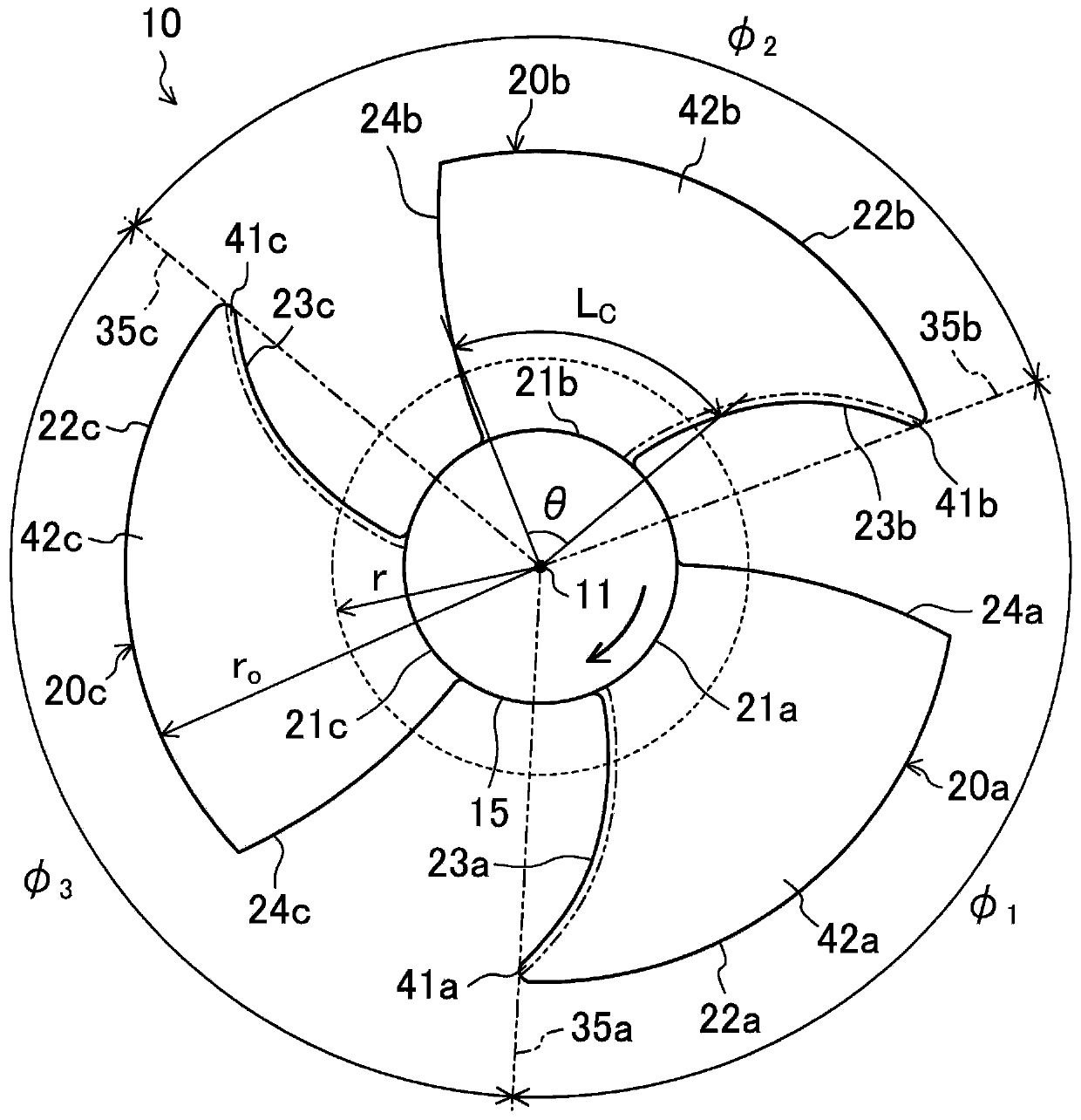
[0039] The first embodiment will be described. The propeller fan 10 of this embodiment is an axial flow fan. The propeller fan 10 is installed, for example, in a heat source unit of an air conditioner, and is used to supply outdoor air to a heat source side heat exchanger.
[0040] -Structure of Propeller Fan-
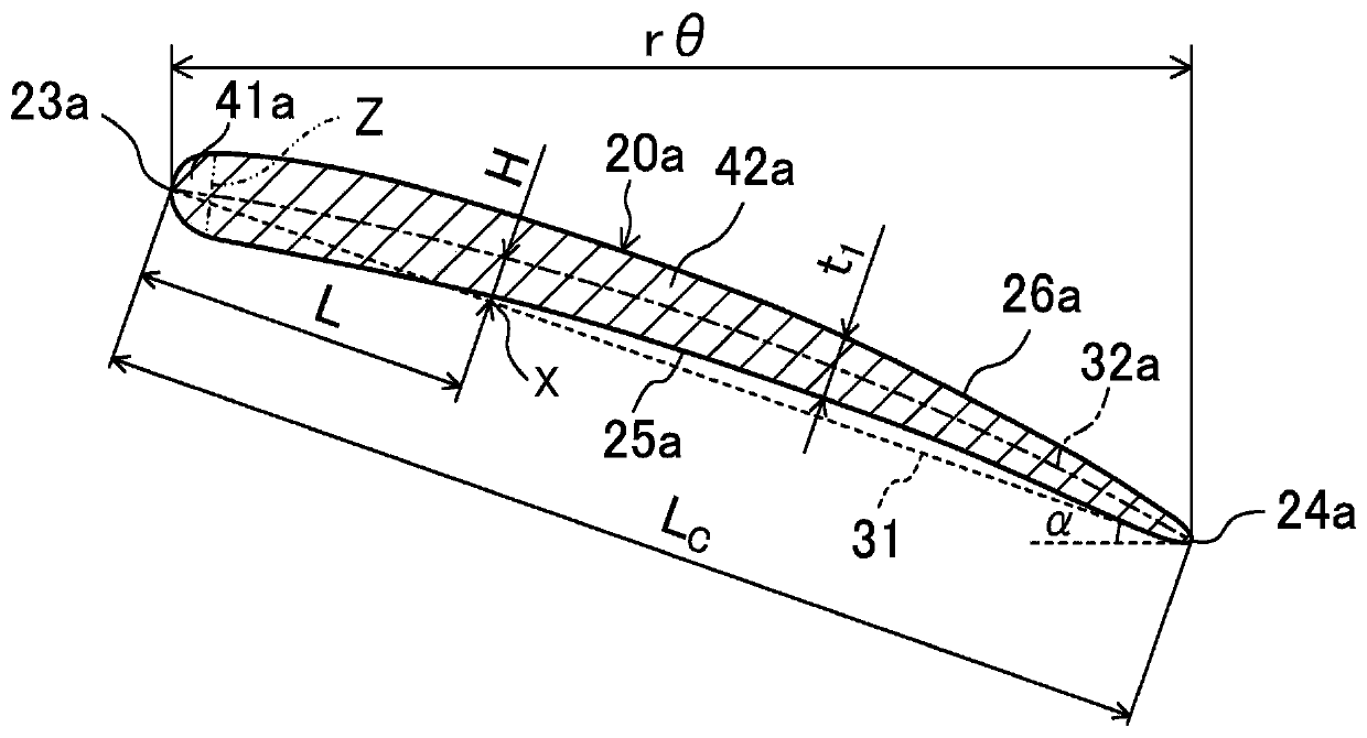
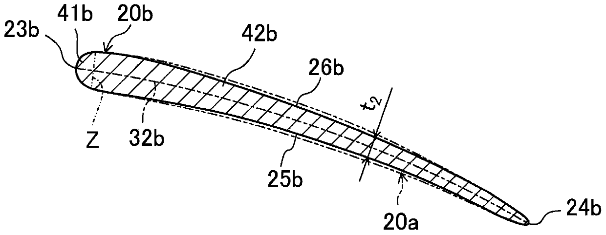
[0041] Such as figure 1 As shown, the propeller fan 10 of this embodiment includes a hub 15 and three blades 20a, 20b, 20c. One hub 15 is integrally formed with three blades 20a to 20c. The propeller fan 10 is made of resin.
[0042] The hub 15 is formed in a cylindrical shape with a closed front end. The hub 15 is mounted on the drive shaft of the fan motor. The center axis of the hub 15 is the rotation center axis 11 of the propeller fan 10 .
[0043] The blades 20 a to 20 c are arranged to protrude outward from the outer peripheral surface of the hub 15 . The three blades 20 a to 20 c are arranged at predetermined intervals in the circumferential direction o...
no. 2 approach
[0087] A second embodiment will be described. In the propeller fan 10 of the present embodiment, the shapes of the blades 20 a to 20 c are changed from the propeller fan 10 of the first embodiment. Here, differences between propeller fan 10 of the present embodiment and propeller fan 10 of the first embodiment will be described.
[0088] Such as Figure 4A ~ Figure 4CAs shown, swelling portions 45a, 45b, and 45c are formed on the blades 20a to 20c of the present embodiment. The bulging portions 45a to 45c are portions swollen toward the positive pressure surfaces 25a to 25c of the blades 20a to 20c, and extend along the leading edge portions 41a to 41c across the entire length of the leading edge portions 41a to 41c. The surfaces of the raised portions 45a to 45c are convex surfaces that are smoothly connected to the surfaces of the regions adjacent to the raised portions 45a to 45c of the blades 20a to 20c. The shapes of the swelling parts 45a to 45c of the respective blad...
other Embodiment approach
[0091] In the propeller fan 10 of each of the above-mentioned embodiments, the number of the blades 20 a to 20 c may be an odd number of five or more. Moreover, in the propeller fan 10 of each embodiment mentioned above, the number of blades 20a-20c may be an even number.
[0092] In addition, the propeller fan 10 of each of the above-mentioned embodiments may be such that not all blades but some blades have different circumferential angles and masses.
[0093] Furthermore, in the propeller fan 10 according to the first embodiment described above, the shapes of the respective arcs 32 a to 32 c of the respective blades 20 a to 20 c and the respective projections on a plane perpendicular to the rotation central axis 11 of the propeller fan 10 The shape in the drawing and the shapes of the respective front edge portions 41 a to 41 c may be consistent with each other. Regarding the "shape of the arcs 32a to 32c", "shape of the projected view projected on a plane perpendicular to ...
PUM
 Abstract
Description
Claims
Application Information
 - R&D
- Intellectual Property
- Life Sciences
- Materials
- Tech Scout
- Unparalleled Data Quality
- Higher Quality Content
- 60% Fewer Hallucinations
Browse by: Latest US Patents, China's latest patents, Technical Efficacy Thesaurus, Application Domain, Technology Topic, Popular Technical Reports.
© 2025 PatSnap. All rights reserved.Legal|Privacy policy|Modern Slavery Act Transparency Statement|Sitemap|About US| Contact US: help@patsnap.com


