Parapet wall waterproof structure and construction method thereof
A waterproof structure and construction method technology, applied to building components, building structures, roof insulation materials, etc., can solve problems such as roof leakage and wall damage, achieve structural stability, enhance waterproof performance, and reduce slight downward movement Effect
- Summary
- Abstract
- Description
- Claims
- Application Information
AI Technical Summary
Problems solved by technology
Method used
Image
Examples
Embodiment 1
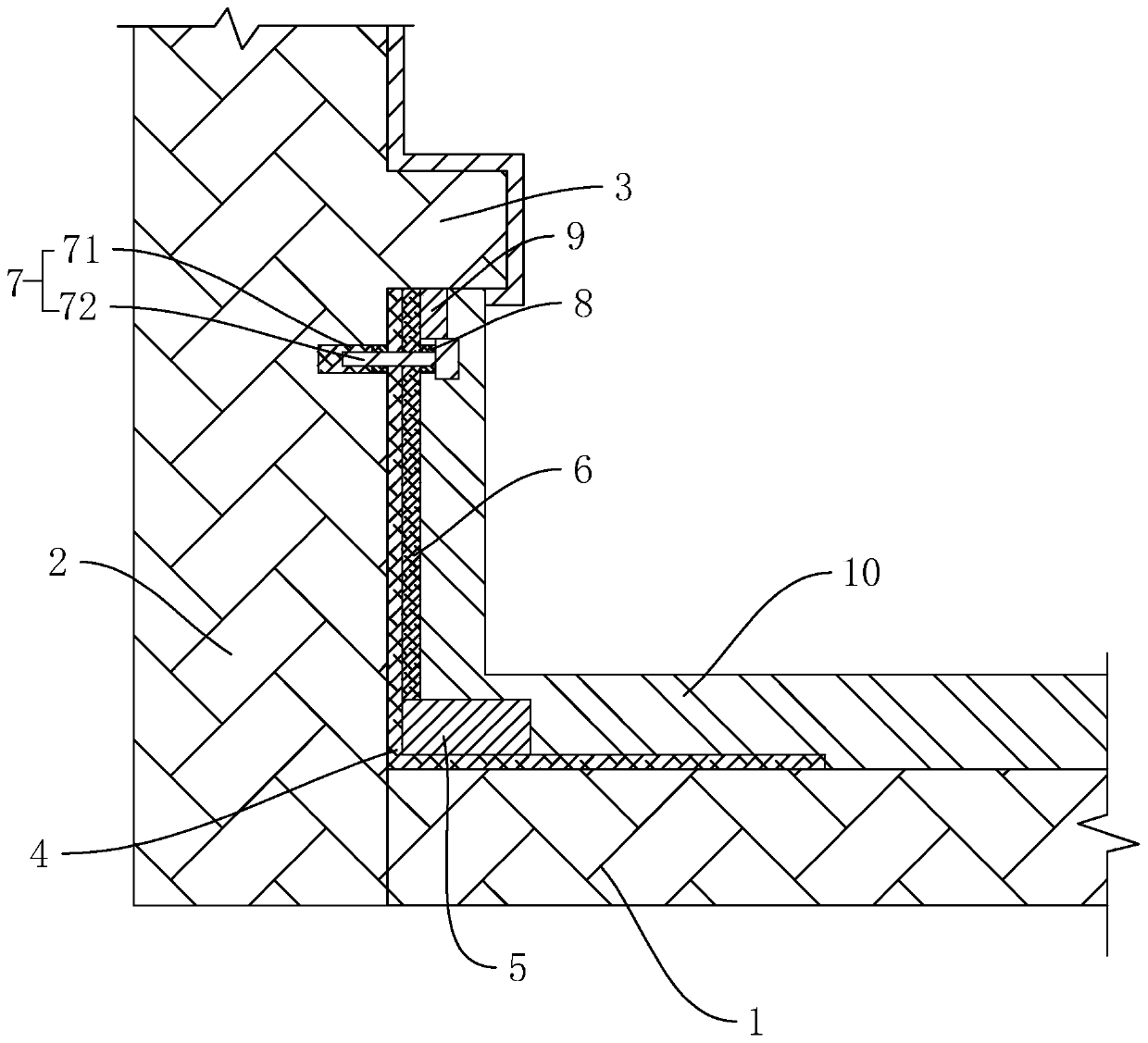
[0040] A parapet waterproof structure, such as figure 1 As shown, it is mainly applied to the joint between the roof panel 1 and the wall 2. The waterproof structure includes a raised strip 3 preset on the inner side of the wall body 2 , and usually the height of the raised strip 3 is about 350 mm from the upper end surface of the roof panel 1 . The raised strip 3 extends horizontally corresponding to the wall body 2 , and the cross section of the raised strip 3 is arranged in a square shape. The junction of the roof panel 1 and the wall 2 is also laid with a waterproof coiled material 4 , and the sides of the waterproof coiled material 4 are attached to the inner side of the wall body 2 and the upper end surface of the roof panel 1 at the same time.
[0041] The upper end surface of the roof panel 1 is also provided with a sealing plate 5 , the sealing plate 5 is located on the upper end surface of the waterproof coiled material 4 , and the sealed plate 5 interferes with the...
Embodiment 2
[0046] A construction method for a parapet waterproof structure, comprising the following steps:
[0047] S1: Cleaning up, leveling the bumps on the wall surface and the roof panel 1, and cleaning up the sundries.
[0048] S2: Leveling, use 1:3 cement mortar to level the upper end surface of the roof panel 1 and the inward side of the wall, so that the side wall facing inward and lower than the raised strip 3 and the upper end surface of the roof panel 1 are flat.
[0049] S21: Embed plastic embedded parts 71, drill holes at 50-60 mm below the lower end surface of the convex strip 3, drill one at intervals of 500 mm along the horizontal direction, and then embed plastic embedded parts 71 in it, and each plastic embedded part 71 is close to the wall One end of the surface is bonded with a rubber backing ring 8, the rubber backing ring 8 is coaxially arranged with the plastic embedded part 71, and the end face of the rubber backing ring 8 away from the plastic embedded part 71 i...
PUM
 Abstract
Description
Claims
Application Information
 - R&D
- Intellectual Property
- Life Sciences
- Materials
- Tech Scout
- Unparalleled Data Quality
- Higher Quality Content
- 60% Fewer Hallucinations
Browse by: Latest US Patents, China's latest patents, Technical Efficacy Thesaurus, Application Domain, Technology Topic, Popular Technical Reports.
© 2025 PatSnap. All rights reserved.Legal|Privacy policy|Modern Slavery Act Transparency Statement|Sitemap|About US| Contact US: help@patsnap.com

