High frequency precision harmonic reducer

A harmonic reducer, precise technology, applied in transmission parts, belt/chain/gear, mechanical equipment, etc., can solve the problem of hindering the development of high-frequency harmonic reducer, the vibration of the harmonic reducer is large, and it is not enough to reduce Vibration and other problems, to achieve the effect of improving precision transmission capacity, sufficient meshing, and reducing vibration

Pending Publication Date: 2020-01-31
SUZHOU LEADERDRIVE HARMONIC WAVE TRANSMISSION TECH CO LTD
View PDF0 Cites 0 Cited by
  • Summary
  • Abstract
  • Description
  • Claims
  • Application Information

AI Technical Summary

Problems solved by technology

[0006] Since the wave generator rotates once, there will be at least two staggered tooth movements, or even more than three staggered tooth movements, the vibration during the transmission process will be higher than the frequency of the previous harmonic reducer, and then the wave will be generated. The contact frequency between the convex structure of the cam of the device and the inner surface of the ring gear of the flexspline is high. The flange of the existing flexspline only connects the axial inner end of the ring cloth tooth structure of the flexspline through a radial thin wall. In order to reduce the vibration caused by high-frequency contact, the vibration of the entire harmonic reducer is relatively large and cannot be used for precision transmission, which hinders the development of high-frequency harmonic reducer

Method used


Image

  • High frequency precision harmonic reducer
  • High frequency precision harmonic reducer

Examples


Embodiment Construction

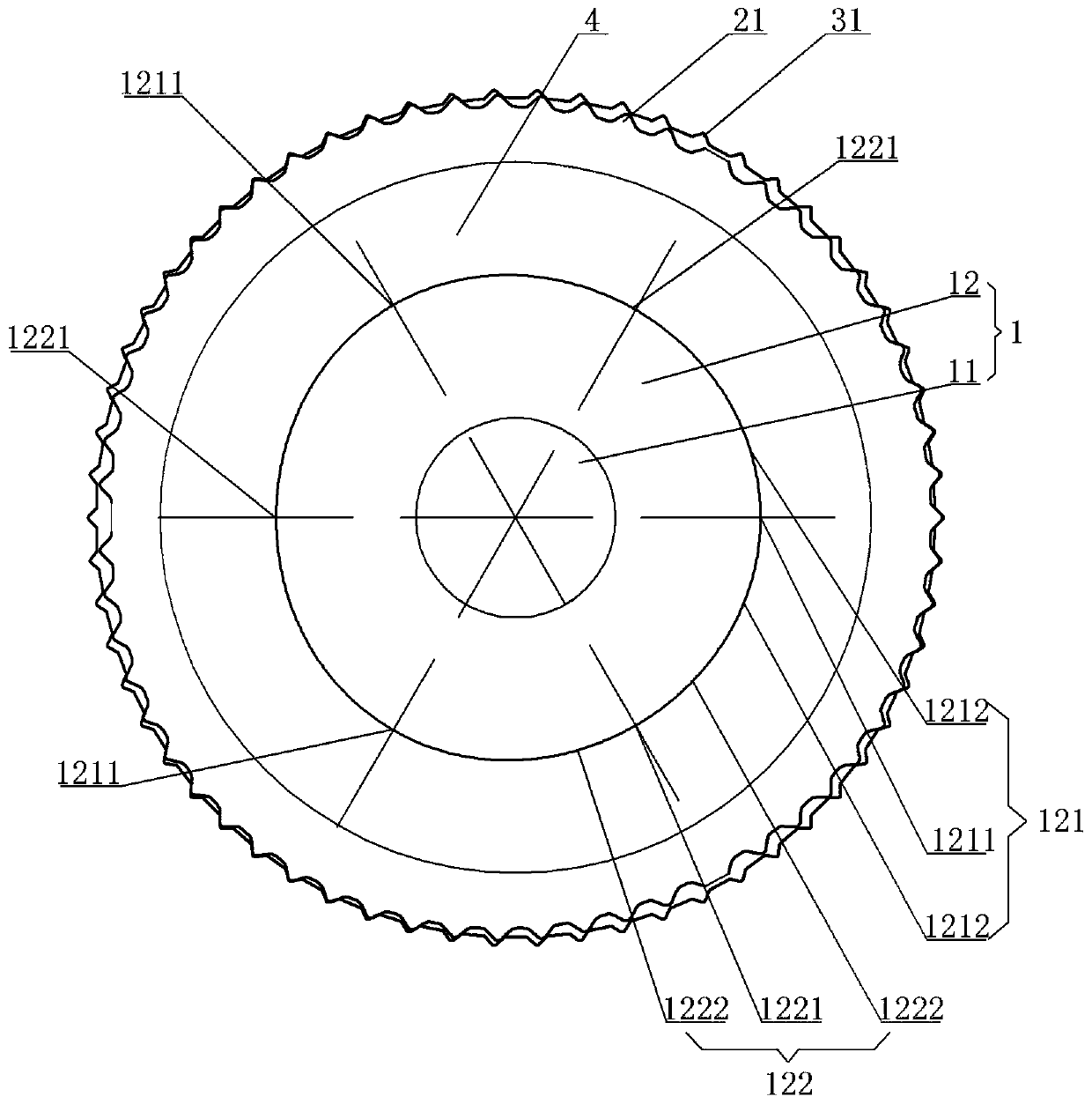
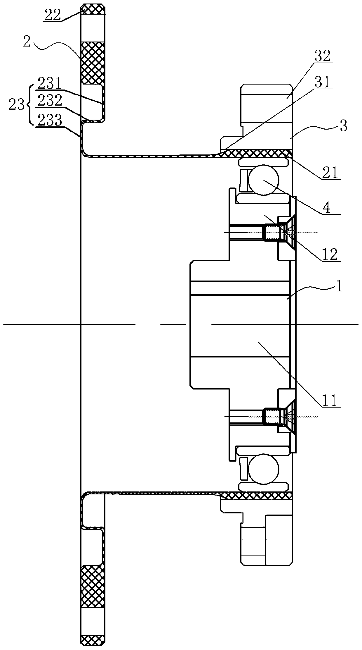
[0021] A high-frequency precision harmonic reducer, see Figure 1-Figure 2 : It includes a wave generator 1, a flex spline 2, and a rigid spline 3. The flex spline 2 includes a flexible internal gear 21, an output flange 22, and a radial connection part 23. The wave generator 1 is built into the internal installation cavity of the flexible internal gear 21 Arranged internally, the wave generator 1 includes an input shaft end 11, a cam 12, and a ring cloth flexible bearing 4 between the outer peripheral surface of the cam 12 and the inner peripheral surface of the flexible internal gear 21. The cam 12 of the wave generator 1 is specifically N convex structure, the outer circumference of the cam 12 is evenly distributed with N convex ring surfaces 121, wherein N is a natural number greater than or equal to 2, and a progressive transition ring surface 122 is provided between adjacent convex ring surfaces 121, flexible The teeth of the inner gear 21 mesh with the corresponding out...


PUM


Abstract

The invention provides a high frequency precision harmonic reducer. A flexible wheel in a process of being engaged to a cam can counteract and eliminate corresponding vibration, so that vibration of the whole reducer is alleviated, the service life of the whole reducer is prolonged, the noise of the whole reducer is reduced, and the whole reducer is more stable in transmission, more full to engageand improves the precise transmission ability. The high frequency precision harmonic reducer comprises a wave generator, the flexible wheel and a rigid wheel. The flexible wheel comprises a flexibleinner gear, an output flange and a radial connecting part. The wave generator is arranged in an inner mounting cavity of the flexible inner gear. The wave generator comprises an input shaft end and acam. Flexible bearings are annularly distributed between the outer annular circumferential surface of the cam and the inner annular circumferential surface of the flexible inner gear, the cam of the wave generator is specifically of a N-convex structure, N convex ring surfaces are annularly distributed on the outer annular circumference of the cam uniformly, N is a natural number greater than or equal to 2, a progressive transitional annular surface is arranged between two adjacent convex ring surfaces, and the gear part of the flexible inner gear is in engaged connection to a corresponding outer gear of the rigid wheel.

Description

technical field [0001] The invention relates to the technical field of harmonic reducers, in particular to a high-frequency precision harmonic reducer. Background technique [0002] Harmonic reducers have been widely used in electronics, aerospace, robotics and other industries due to their advantages of high load capacity, large transmission ratio, small size, light weight, stable transmission and high transmission precision. [0003] In the existing harmonic reducer, when the wave generator is installed in the internal gear, the internal gear is forced to deform elastically and become elliptical, thereby generating a secondary frequency and producing the so-called two staggered tooth movements, thereby realizing active wave generation The motion transmission of the device and the flexible spline. [0004] However, in the existing harmonic reducer structure, due to the small meshing contact surface between the teeth and the eating surface during the transmission process, t...

Claims


Application Information

Patent Timeline
Patent Type & Authority Applications(China)
IPC IPC(8): F16H49/00F16H57/023F16H57/028
CPCF16H49/001F16H57/023F16H57/028
Inventor 左昱昱庄晓琴
Owner SUZHOU LEADERDRIVE HARMONIC WAVE TRANSMISSION TECH CO LTD
Why Eureka
Try Eureka