Discharging structure of waste dryer

A dryer and garbage technology, applied in the direction of drying solid materials, drying, dryers, etc., can solve the problems of irregularity, bridging, changing physical shapes, etc., to achieve convenient processing, simple structure, and smooth discharge. Effect

Pending Publication Date: 2020-01-31
深圳龙澄高科技环保股份有限公司
View PDF0 Cites 0 Cited by
  • Summary
  • Abstract
  • Description
  • Claims
  • Application Information

AI Technical Summary

Problems solved by technology

Due to the complex composition of the waste and the changeable and irregular physical shape, the discharge process is often not smooth enough, and it is even squeezed at the end by the screw, resulting in bridging and material blocking problems.

Method used


Image

  • Discharging structure of waste dryer

Examples


Embodiment Construction

[0009] In order to make the objectives, technical solutions and advantages of the present invention more clear, the technical solutions in the implementation of the present invention will be described in more detail below in conjunction with the drawings in the embodiments of the present invention. The described embodiments are some of the embodiments of the present invention, and are intended to explain the present invention, rather than all embodiments, and should not be construed as limiting the present invention. The present invention will be described in further detail below in conjunction with the accompanying drawings.

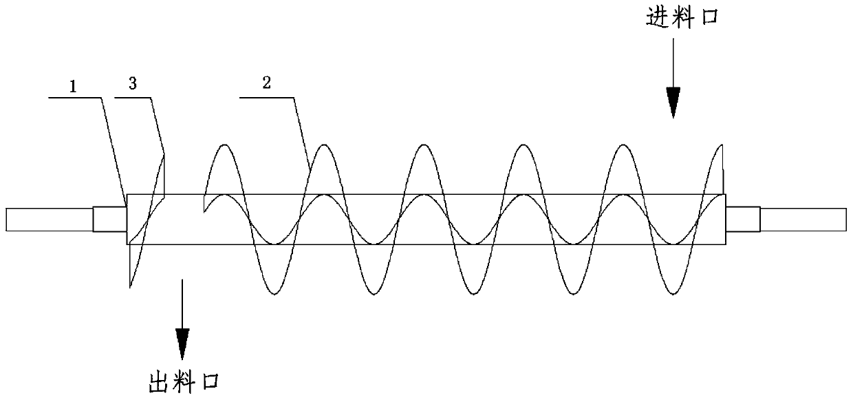
[0010] Such as figure 1 As shown, a garbage dryer discharge structure, including 1-central shaft, 2-feeding screw, 3-reverse screw.

[0011] In this embodiment, the 2-feeding helix is ​​welded at the front section of the 1-central axis, and the 3-reversed helix is ​​welded at the discharge port at the end of the 1-central axis.

[0012] The 2-feeding ...


PUM


Abstract

The invention provides a discharging structure of a waste dryer. The discharging structure comprises a central shaft, a feeding spiral and a reverse spiral. The feeding spiral is welded to the front section of the central shaft to push waste to move. The reverse spiral is welded to the tail end of the central shaft. The reverse spiral and the feeding spiral are distributed on the two sides of a discharging opening. Under the squeezing effect of the reverse spiral and the feeding spiral, the waste can be smoothly discharged from the discharging opening, and the problem of bridging and blockingof the waste material discharging opening is solved.

Description

technical field [0001] The invention belongs to the technical field of material drying, and in particular relates to a discharge structure of a garbage dryer. Background technique [0002] A garbage dryer, the material conveying design refers to the screw conveyor and the paddle dryer, the garbage is propelled by the screw in the dryer, and is discharged from the discharge port after drying. Due to the complex composition of the waste and the changeable and irregular physical shape, the discharge process is often not smooth enough, and it is even squeezed at the end by the screw, resulting in bridging and material blocking problems. Contents of the invention [0003] The invention provides a discharge structure of a garbage dryer to solve the discharge problem in the prior art. [0004] The technical solution adopted in the present invention is: a discharge structure of a garbage dryer is provided, which includes a central shaft, a feeding screw and a reverse screw. [0...

Claims


Application Information

Patent Timeline
Patent Type & Authority Applications(China)
IPC IPC(8): F26B25/04F26B17/20
CPCF26B17/20F26B25/04
Inventor 龚佰勋黎莉陈洪一倪彬邓晨
Owner 深圳龙澄高科技环保股份有限公司
Why Eureka
Try Eureka