Hybrid-type stepping motor

A technology of stepping motor and stator yoke, which is applied to electrical components, electromechanical devices, etc., can solve problems such as difficulty in coil winding

Inactive Publication Date: 2003-04-30
TAMAGAWA SEIKI CO LTD
View PDF0 Cites 0 Cited by
  • Summary
  • Abstract
  • Description
  • Claims
  • Application Information

AI Technical Summary

Problems solved by technology

This arrangement makes co

Method used


Image

  • Hybrid-type stepping motor
  • Hybrid-type stepping motor
  • Hybrid-type stepping motor

Examples


Embodiment Construction

[0044] With reference to the accompanying drawings, the compound stepping motor of the present invention is now discussed. Parts identical or equivalent to those of the prior art are indicated with the same reference numerals.

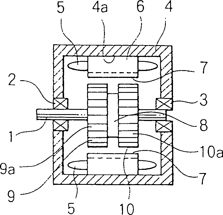
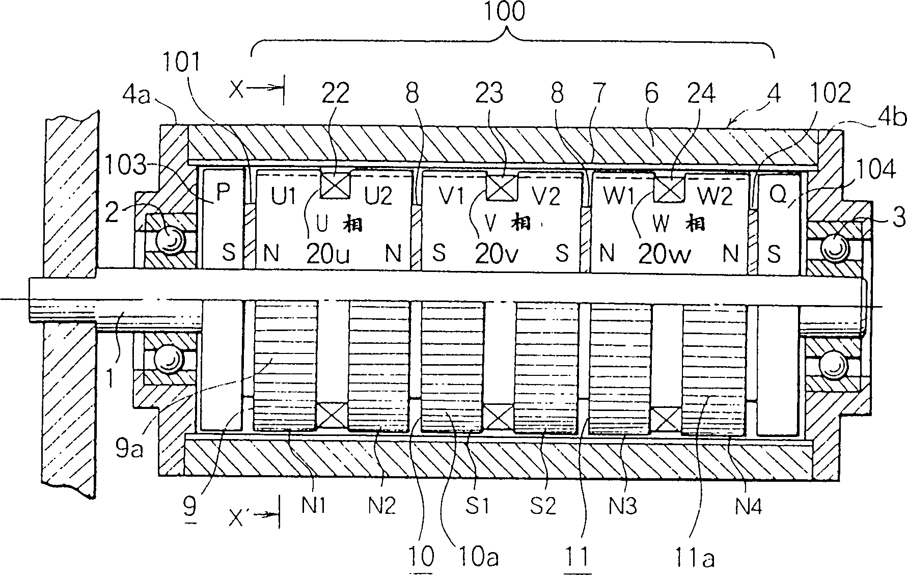
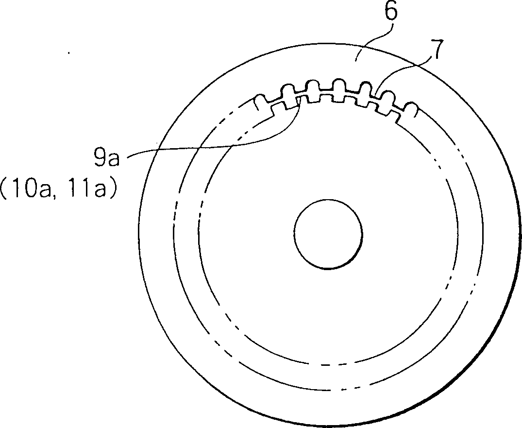
[0045] figure 2 A compound stepper motor with an outer rotor structure is shown. Reference numeral 1 is a fixed shaft made of non-magnetic material, on which a pair of bearings 2, 3 spaced apart from each other are housed. A rotor housing 4 composed of a front end cover 4 a , a rear end cover 4 b and a cylindrical rotor yoke 6 is rotatably supported on bearings 2 , 3 . A plurality of rotor teeth 7 are arranged on the inner circumference of the rotor yoke 6 of the rotor housing 4 .

[0046] The first, second and third annular stator yokes 9, 10, 11 together with the flat magnets 8 sandwiched therebetween are arranged side by side along the direction of the fixed axis on the fixed axis 1 to form a whole including the flat magnets 8. The circumferences ...


PUM


Abstract

A hybrid-type stepping motor having coils on stator yokes mounted on a fixed shaft or coils wound on the inner circumferences of stator yokes. The hybrid-type stepping motor is easy to coil wind, offers a substantially high density of coils, and achieves a cost reduction. The use of sub cylinder magnets and sub magnetic flanges on both sides of a stator yoke body allows magnetic circuits to form on both sides of the stator yoke body. This arrangement results in an increase in torque. A multiple-phase motor is easily constructed.

Description

technical field [0001] The present invention relates to a compound stepping motor, and more particularly, relates to a new improvement of the compound stepping motor, which facilitates the winding and placement of the coil, and enables the coil to achieve high density to obtain a high-efficiency and low-cost structure, And it can be driven by any number of phases, such as two-phase, three-phase and five-phase. Background technique [0002] As shown in FIG. 1 , the prior art differential motor has a rotating shaft 1 rotatably supported on a pair of bearings 2 and 3 fastened to both ends of a housing 4 . Attached to the inner surface of the stator housing 4 is a generally annular stator yoke 6 carrying the stator coils 5 . A plurality of stator teeth 7 are arranged at regular intervals on the inner circumference of the stator yoke 6 . Between the two bearings 2, 3 there are two annular first and second rotor yokes 9, 10 arranged in one body on the rotating shaft and a flat m...

Claims


Application Information

Patent Timeline
IPC IPC(8): H02K37/20
CPCH02K37/20H02K37/00
Inventor 杉浦恒雄
Owner TAMAGAWA SEIKI CO LTD
Why Eureka
Try Eureka