Material positioning moving rod detection mechanism

A technology of movable rods and materials, applied in metal processing, metal processing equipment, manufacturing tools, etc., can solve problems such as large shaking, poor detection accuracy, and potential safety hazards, so as to reduce the number of inspections, increase the contact area, and improve The effect of detection accuracy

Pending Publication Date: 2020-02-04
SOUEAST
View PDF0 Cites 0 Cited by
  • Summary
  • Abstract
  • Description
  • Claims
  • Application Information

AI Technical Summary

Problems solved by technology

[0002] In the field of mechanical equipment, since the material is put into the mold in the automatic stamping production line, a positioning detector that can locate and detect is required. The detection positioner currently used is detected by the movable rod next to it. The contact surface of the movable rod is relatively small, and the maximum contact area is only the end face of the movable rod. The material is easy to shake when it is put into the mold, and the amount of shaking is large, which reduces the contact area between the material and the movable rod, resulting in poor detection accuracy and often causing failures on the stamping line. It is detected that there is material in the mold, and personnel need to enter the stamping machine for manual operation to detect it, resulting in low efficiency of the automated production line, and there are also potential safety hazards for personnel entering the stamping machine

Method used


Image

  • Material positioning moving rod detection mechanism
  • Material positioning moving rod detection mechanism
  • Material positioning moving rod detection mechanism

Examples


Embodiment Construction

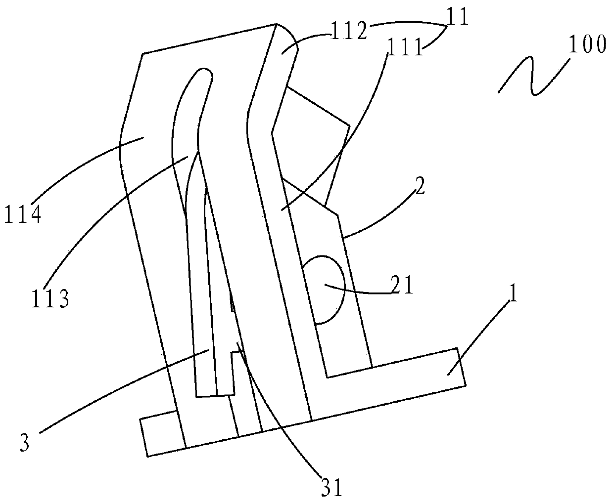
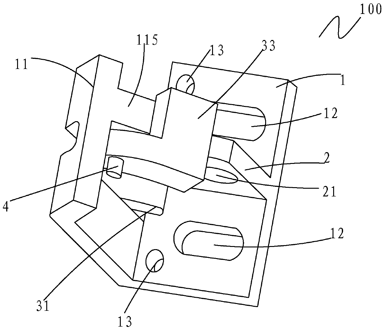
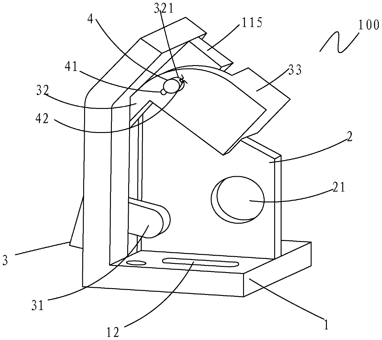
[0028] see Figures 1 to 4 shown.

[0029] The present invention provides a material positioning movable rod detection mechanism 100, including

[0030] The base 1, the left end of the base 1 is provided with a movable rod mount 11; the movable rod mount 11 includes a vertical plate 111 and a guide plate 112; the guide plate 112 is connected to the top of the vertical plate 111, And the guide plate 112 is inclined to the upper right, so that the left side 114 of the guide plate and the vertical plate 111 serves as a guiding sensing surface, and has a guiding function, and the material 5 slides in from the left side of the guide plate 111. In the mold, compared with the existing only one movable rod, the present invention increases the contact area between the material and the movable rod mounting seat 11, so that the material 5 slides in more smoothly, reduces the shaking amount, and improves the detection accuracy; The movable rod mounting seat 11 is provided with a through...


PUM


Abstract

The invention provides a material positioning moving rod detection mechanism. The material positioning moving rod detection mechanism comprises a base, a detector mounting base and a detection movingrod, wherein a moving rod mounting base is arranged at the left end of the base; the moving rod mounting base comprises a vertical plate and a guide plate; the left side surfaces of the guide plate and the vertical plate are used as guide induction surfaces, and the area of the guide induction surfaces is larger than that of the moving rod, so that the contact area is increased, the shaking amountis reduced, the detection precision is improved, the number of times of detecting by a person entering a stamping machine is reduced, and the safety is improved. A through groove has a guide limitingfunction on the detection moving rod, and the shaking amount of the detection moving rod is limited by the width of the through groove. When the detection moving rod is in a natural state, the bottomend of the detection moving rod extends out of the left end surface of the moving rod mounting base from the through groove, so that when the detection moving rod is put into a mold, a detection device senses a detection induction piece, namely, the material is detected in the mold, and after the material is taken away, the detection moving rod is automatically reset.

Description

technical field [0001] The invention relates to the field of mechanical detection equipment, in particular to a material positioning movable rod detection mechanism. Background technique [0002] In the field of mechanical equipment, since the material is put into the mold in the automatic stamping production line, a positioning detector that can locate and detect is required. The detection positioner currently used is detected by the movable rod next to it. The contact surface of the movable rod is relatively small, and the maximum contact area is only the end face of the movable rod. The material is easy to shake when it is put into the mold, and the amount of shaking is large, which reduces the contact area between the material and the movable rod, resulting in poor detection accuracy and often causing failures on the stamping line. It is detected that there is material in the mold, and it needs personnel to enter the stamping machine for manual operation to detect it, re...

Claims


Application Information

Patent Timeline
IPC IPC(8): B21C51/00B21D55/00
CPCB21C51/00B21D55/00
Inventor 孙梓清周兆塔
Owner SOUEAST
Why Eureka
Try Eureka