Driven type lower limb motion force assisting exoskeleton device

A passive, exoskeleton technology, applied in manipulators, program-controlled manipulators, manufacturing tools, etc., can solve problems such as increasing the tension spring force of the steel wire rope, breaking the wire rope, increasing exercise load and discomfort, and achieving the effect of avoiding friction

Active Publication Date: 2020-02-04
CHONGQING UNIV OF TECH
View PDF8 Cites 15 Cited by
  • Summary
  • Abstract
  • Description
  • Claims
  • Application Information

AI Technical Summary

Problems solved by technology

The above-mentioned passive knee assist device has the following problems in actual use: 1. The steel wire rope is sleeved on the disc structure. It slides and has friction, and long-term use will cause the steel wire rope to break under the action of the friction, which will damage the entire knee joint passive power-assisted device; 2. When the human body wearing the power-assisted device walks on a flat road withou

Method used


Image

  • Driven type lower limb motion force assisting exoskeleton device
  • Driven type lower limb motion force assisting exoskeleton device
  • Driven type lower limb motion force assisting exoskeleton device

Examples


Embodiment 1

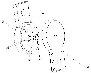
[0052] as attached image 3 And attached Figure 4 As shown, in this embodiment, there is one torsion spring 9, and the torsion spring 9 is sleeved on the first protrusion 31, and one end of the torsion spring 9 is fixed on the thigh connecting plate 3 as a fixed end, and the other end of the torsion spring 9 As a movable end, a first limit protrusion 11 is provided on the shank connection plate 4, and the movable end of the torsion spring 9 is aligned with the first limit protrusion when the relative rotation angle of the thigh connection plate 3 and the shank connection plate 4 reaches a set value. From 11 to offset.

[0053] In this way, the torsion spring 9 is sleeved on the first protrusion 31, and one end of the torsion spring 9 is fixed on the thigh connection plate 3. When the human leg is bent, the first protrusion 31 on the thigh connection plate 3 drives the torsion spring 9 rotates around the shank connection plate 4, when the relative rotation angle of the thigh...

Embodiment 2

[0067] The difference between embodiment two and embodiment one is:

[0068] as attached Figure 5 And attached Figure 6 As shown, in the present embodiment, there is one torsion spring 9, and the torsion spring 9 is sleeved on the second protrusion 41, and one end of the torsion spring 9 is fixed on the shank connecting plate 4 as a fixed end, and the other end of the torsion spring 9 As a movable end, a second position-limiting protrusion 12 is provided on the thigh connection plate 3, and the movable end of the torsion spring 9 is aligned with the second position-limiting protrusion when the relative rotation angle of the thigh connection plate 3 and the shank connection plate 4 reaches a set value. From 12 to offset.

[0069] In this way, the torsion spring 9 is sleeved on the second protrusion 41, and one end of the torsion spring 9 is fixed on the shank connection plate 4. When the human leg is bent, the second protrusion 41 on the shank connection plate 4 drives the ...

Embodiment 3

[0075] The difference between embodiment three and embodiment one is:

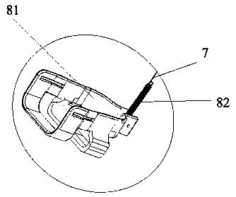
[0076] as attached Figure 7 And attached Figure 8 As shown, in this embodiment, there are two torsion springs 9, and the two torsion springs 9 are respectively sleeved on the first protrusion 31 and the second protrusion 41, and the lower leg connection plate 4 is provided with a first stop protrusion. 11, the thigh connection plate 3 is provided with a second limit protrusion 12, and one end of the torsion spring 9 sleeved on the first protrusion 31 is fixed on the thigh connection plate 3 as a fixed end, and is sleeved on the first protrusion 31. The other end of the torsion spring 9 on the lifter 31 is used as a movable end when the relative rotation angle of the thigh connection plate 3 and the shank connection plate 4 reaches a set value, and the first stop protrusion 11 is offset;

[0077] One end of the torsion spring 9 sleeved on the second protrusion 41 is fixed on the shank connection plate 4...


PUM


Abstract

The invention discloses a driven type lower limb motion force assisting exoskeleton device. A knee joint force assisting mechanism is included and comprises two knee joint force assisting assemblies,knee joint force assisting assembly thigh connecting discs and shank connecting discs. The thigh connecting discs are provided with first protrusions, and the shank connecting discs are provided withsecond protrusions. A plurality of torsional springs are further included and sleeve the first protrusions and (or) the second protrusions. First limiting protrusions and (or) second limiting protrusions are further included. One ends of the torsional springs serve as fixed ends to be fixed to the thigh connecting discs and (or) the shank connecting discs, the other ends serve as movable ends to abut against the first limiting protrusions and (or) the second limiting protrusions when the relative rotation angle of the thigh connecting discs and the shank connecting discs reaches the set value.By means of the driven type lower limb motion force assisting exoskeleton device, the purposes that assisted force is not provided during walking on the level road, and assisted force is only provided during mountain climbing, stair ascending and descending and other large-angle motions are achieved.

Description

technical field [0001] The invention relates to the technical field of wearable devices, in particular to a passive lower limb movement assisting exoskeleton device. Background technique [0002] An exoskeleton is a structure that can be worn on the human body. It can closely link the behavior of the human body with the kinetic energy of the mechanical system. The different parts are divided into upper limb exoskeleton and lower limb exoskeleton. The upper limb exoskeleton is worn on the upper limb of the human body and mainly provides assistance for the transportation of the upper limb of the human body. The lower limb exoskeleton is worn on the lower limb of the human body and mainly provides assistance for the movement of the lower limb of the human body. [0003] The lower extremity exoskeleton is divided into active lower extremity exoskeleton and passive lower extremity exoskeleton. For example, in the invention patent application document with publication number CN106...

Claims


Application Information

Patent Timeline
IPC IPC(8): B25J9/00
CPCB25J9/0006
Inventor 黎波
Owner CHONGQING UNIV OF TECH
Why Eureka
Try Eureka