
Walking mechanism of steel casting transporting vehicle
A technology of walking mechanism and transport vehicle, which is applied in the direction of transportation and packaging, motion deposition, vehicle parts, etc. It can solve the problems of easy damage of springs, etc., and achieve the effect of improving pressure bearing capacity, strong supporting capacity, and high compressive resistance
- Summary
- Abstract
- Description
- Claims
- Application Information
AI Technical Summary
Problems solved by technology
Method used
Image

Examples
Embodiment Construction
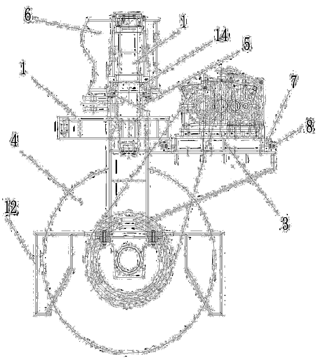
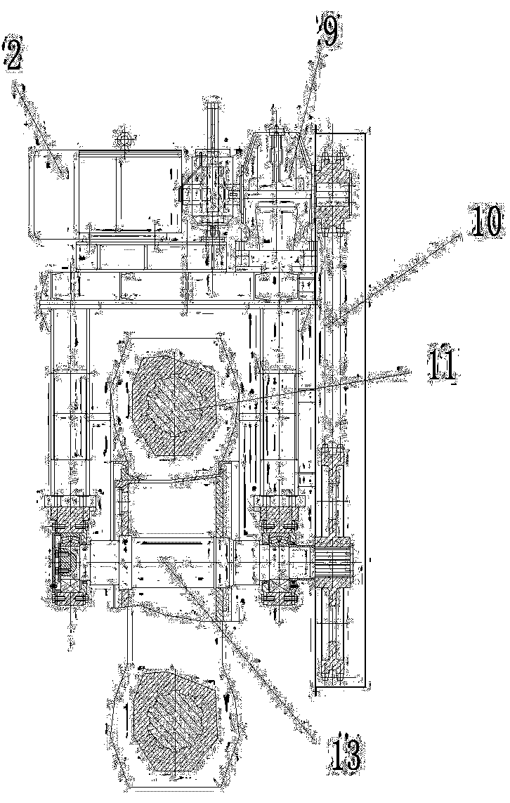
[0010] The specific implementation manner of the present invention will be described in detail below in conjunction with the accompanying drawings and preferred embodiments. Such as Figure 1-Figure 2 As shown, a walking mechanism of a steel casting transport vehicle includes a vehicle frame 1, a motor 2, a movable base 3 and wheels 4. The vehicle frame is provided with a limit hole 5, and the column is inserted into the limit hole, and the bottom of the column passes through the Bolts are fixedly connected with the vehicle frame, the middle part of the upright is closely matched with the limit hole, the upper part of the upright passes through the chassis 6 and is connected through the bearing 14; the upright can be disassembled by setting the limit hole, the upright is connected with the chassis through two bearings, and the bearing Thrust bearings are adopted, which can not only rotate, but also support the upper chassis.
[0011] In order to be able to adjust the movable ...
PUM
 Abstract
Description
Claims
Application Information