Chemical fiber spinning box and application method thereof

A spinning box and chemical fiber technology, applied in the field of fiber manufacturing, can solve problems such as cylinder explosion, fiber quality problems, equipment and operator injuries, etc., and achieve the effects of reducing the probability of damage, facilitating connection, and ensuring quality

Inactive Publication Date: 2020-02-04
福建新创锦纶实业有限公司
View PDF10 Cites 7 Cited by
  • Summary
  • Abstract
  • Description
  • Claims
  • Application Information

AI Technical Summary

Problems solved by technology

[0003] Most of the traditional chemical fiber spinning boxes are extruded by hydraulic pressure, which leads to the need for a hydraulic system. The cost of the hydraulic system on the market is relatively high, and the hydraulic system will explode during the operation of the cylinder, which is easy to damage the equipment. cause harm to operators; at the same time, most of the existing chemical fiber limiters are vertically output, which leads to the fact that the collection mechanism can only be set vertically, which cannot meet the needs of the horizontal collection device; in addition, the traditional spinning box Most of the time, wind blowing is used to cool and shape the molten chemical fiber raw materials. Since the direction of the wind blowing cannot be accurately controlled, it is easy to cause quality problems in the shaped fibers.

Method used


Image

  • Chemical fiber spinning box and application method thereof
  • Chemical fiber spinning box and application method thereof
  • Chemical fiber spinning box and application method thereof

Examples


Embodiment Construction

[0027] The present invention will be further described below in conjunction with the accompanying drawings and embodiments.

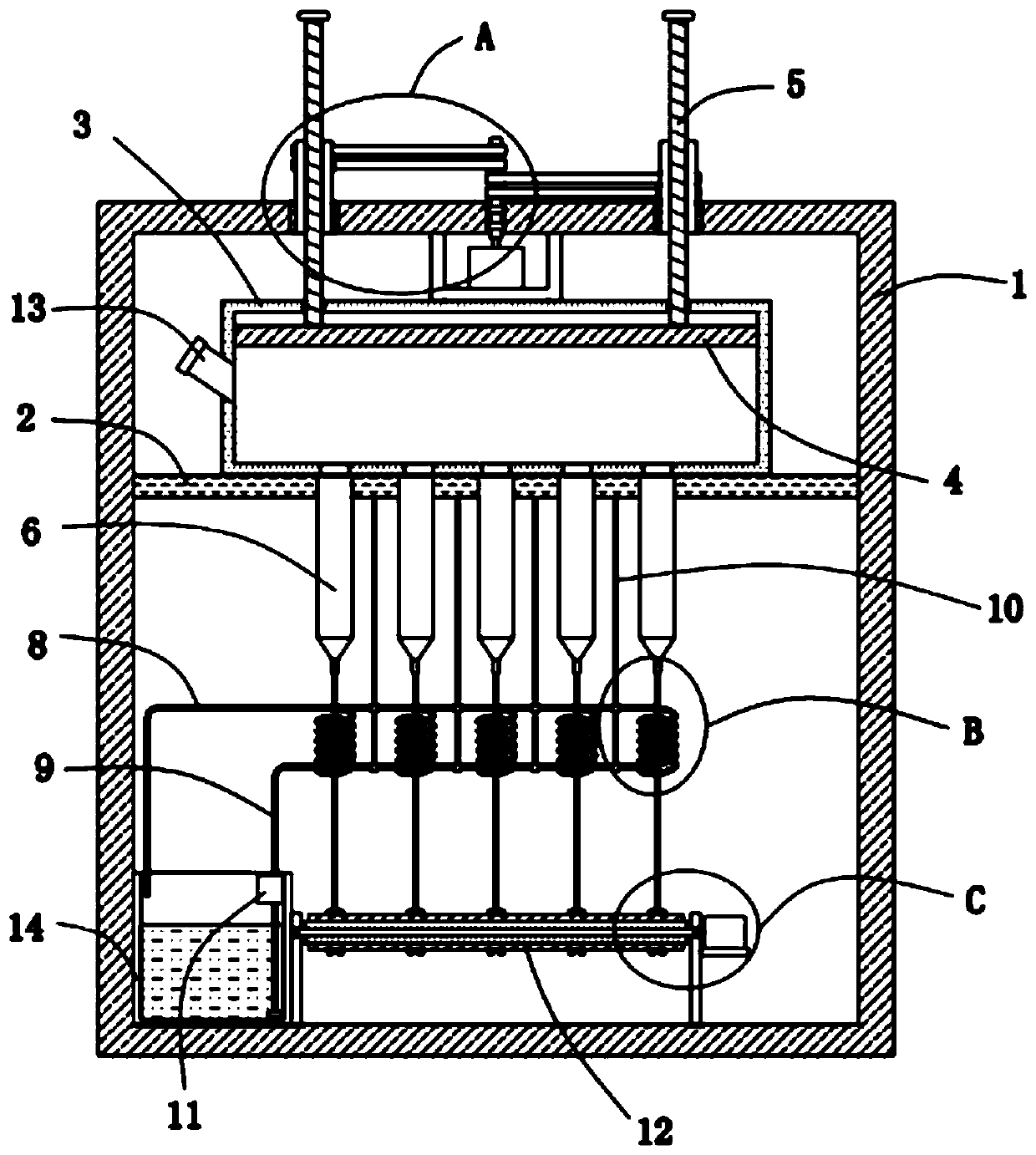
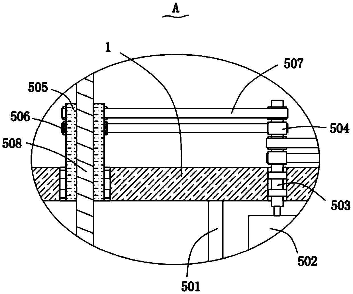
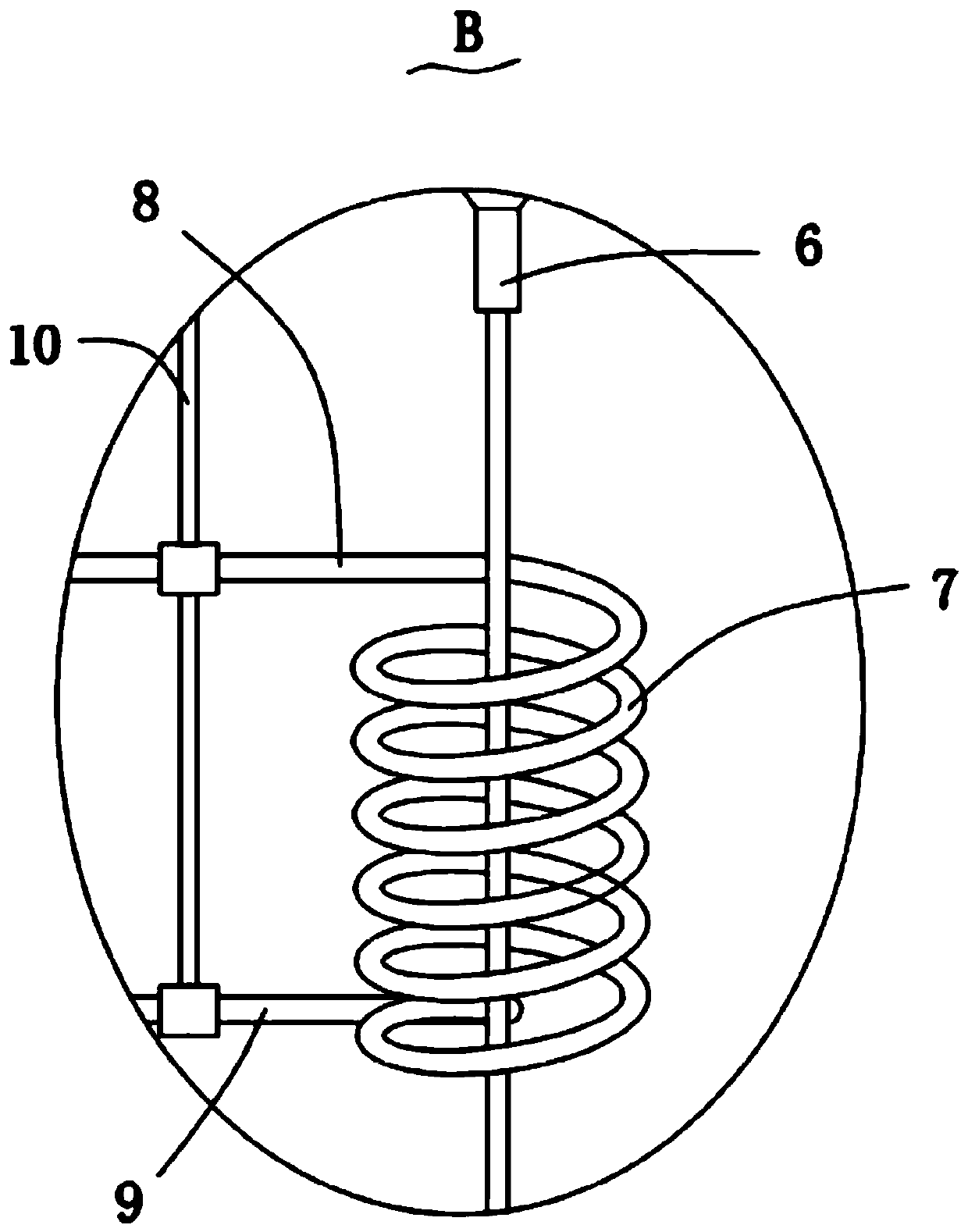
[0028] Please refer to figure 1 , figure 2 , image 3 and Figure 4 ,in, figure 1 Schematic diagram of the structure of the chemical fiber spinning box provided by the present invention; figure 2 for figure 1 An enlarged schematic view of part A shown; image 3 for figure 1 An enlarged schematic view of part B shown; Figure 4 for figure 1 An enlarged schematic of part C is shown. The invention provides a chemical fiber spinning box, comprising: a support frame 1; a support plate 2, the support plate 2 is fixedly installed in the support frame 1; a heating box 3, the heating box 3 is fixedly installed in the The top of the support plate 2; the push plate 4, the push plate 4 is slidably and sealed installed in the heating box 3; the pushing mechanism 5, the pushing mechanism 5 is installed on the supporting frame 1, and the pushing mechanism ...


PUM


Abstract

The invention provides a chemical fiber spinning box and an application method thereof. The chemical fiber spinning box comprises a support frame; a support plate fixedly mounted in the support frame;a heating box fixedly mounted at the top of the support plate; a push plate arranged in the heating box in a slidable and hermetic manner; a pushing mechanism mounted on the support frame and connected with the push plate; a plurality of yarn discharge pipes linearly arranged in the heating box; a plurality of cooling coils respectively positioned below the plurality of yarn discharge pipes; a liquid outgoing pipe connected with one ends of the cooling coils; and a liquid incoming pipe connected with the other ends of the cooling coils. The chemical fiber spinning box and the application method thereof have the advantages of good convenience of use, low cost and good setting effect.

Description

technical field [0001] The invention relates to the technical field of fiber manufacturing, in particular to a chemical fiber spinning box and a method for using the same. Background technique [0002] The spinning box is one of the main parts of the melt spinning machine. After the polymer melt passes through the filter, it enters the spinning box, and is spun by each spinning position after melt distribution and heat preservation. [0003] Most of the traditional chemical fiber spinning boxes are extruded by hydraulic pressure, which requires a hydraulic system, and the cost of the hydraulic system on the market is relatively high, and the hydraulic system will explode during the operation process, which is easy to damage the equipment. cause harm to operators; at the same time, most of the existing chemical fiber limiters are vertically output, which leads to the fact that the collection mechanism can only be set vertically, which cannot meet the needs of the horizontal c...

Claims


Application Information

Patent Timeline
Patent Type & Authority Applications(China)
IPC IPC(8): D01D13/00
CPCD01D13/00
Inventor 林志吉肖郁
Owner 福建新创锦纶实业有限公司
Why Eureka
Try Eureka